Product Description
| name | Professional high-precision molds and injection molded parts10 |
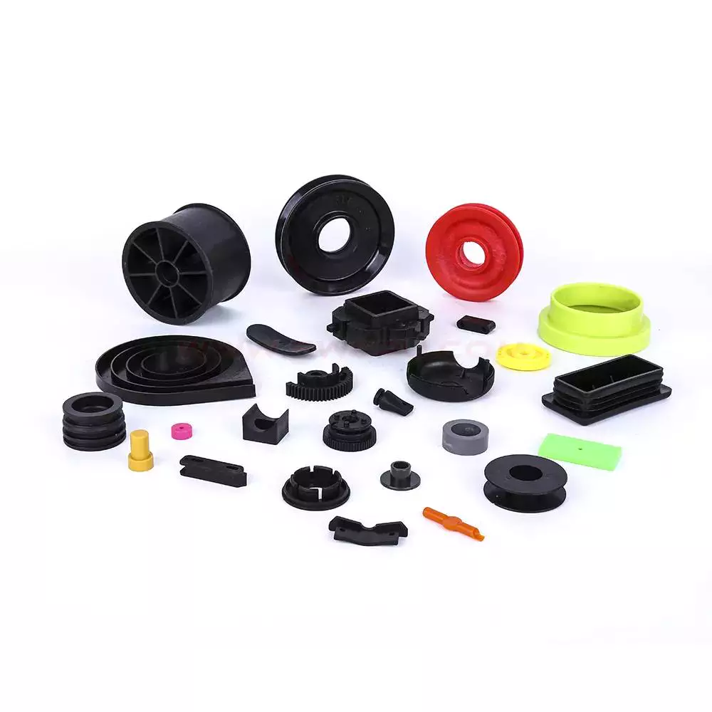
| color | white,black,green,nature,blue,yellow,etc |
| material | ABS,PMMA,PC,PP,PEEK,PU,PA,PA+GF,POM,PE,UPE,PTFE,etc |
| mould cavity | single cavity & multi cavity |
| runner system | hot runner and cold runner |
| equipment | CNC, EDM, cutting off machine,plastic machinery etc |
| mould material | P20/ 718H/ S136H/ S136 hardened/ NAK80 |
| injection machine | 7sets,88T, 90T, 120T, 168T, 2 shots as per customers’ requirement |
| size | 5-1000mm,or customized |
| tolerance | ± 0.05mm |
| shape | as per your drawing or the sample |
| certification | ISO9001 and relate whole set professional test report |
| free sample | available |
| advantage | one stop procurement |
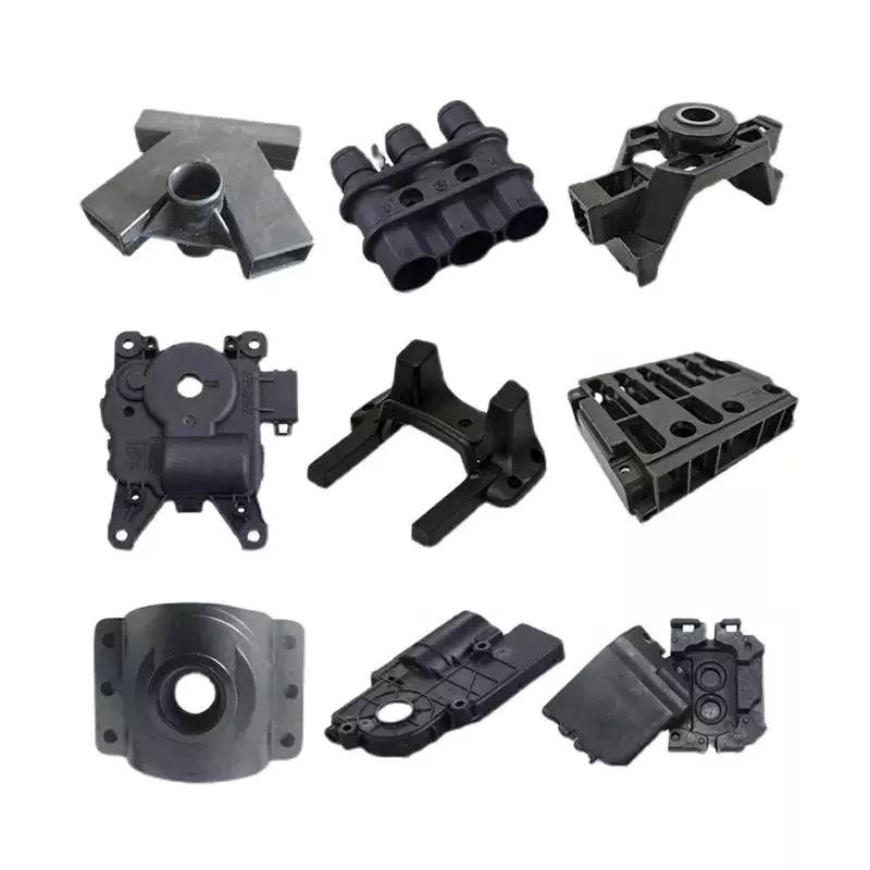
| Application field | Various plastic injection molded parts for various industrial and automotive applications |
| lead time | 25-35 days for mould,plastic products according to quantity |
| other | 24 hours instant and comfortable customer service shipping status notification during delivery regular notification of new styles & hot selling styles |
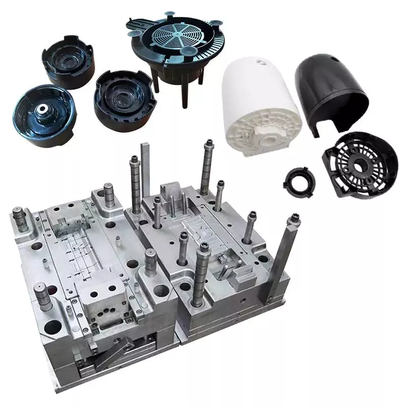
Products Description
Products Show
glossy pattern surface reaction injection molding parts small molded parts injection mold maker ZheJiang Engineering
Plastics Industries,aiming at providing engineering plastics and injection plastic parts. Ccompany owns whole sets of
imported manufacturing machines and advanced CNC machining machines,besides advanced process tools,company
technology are also tremendous. Here is our latest plastic injection project cases , we focus on latest tech and trends
products . We produces products following IOS9001(2000) strictly,the quality conforms to European Union RoHs standards,
Varies of engineering profile:MC NYLON,OIL NYLON,POM,UHMW-PE,PU,PETP,PC,PTFE,PVDF,PEEK,PAI,PI,PBI and
so on! Wide parts processing condition,whole customized production ability, exquisite manufacturing technology and
machines, professional products technology consult and after-sale services.
We have a professional engineer team to design custom parts for your needs , we also have ready-made standard moulds
that can save your cost and time . We offer ODM/OEM service, Production Design and Mould Design base on your
requirement . Providing the sample before mass production , ensure all is OK for you .
Application field
Strength of the company
ZheJiang Engineering Plastics Industries Co., Ltd! We have the professional engineer teams and sales teams, and we
have technology and experiences in engineering plastic industry for morethan 15 years! Our company is located in
Xihu (West Lake) Dis. District, HangZhou City, China, where the logistics is developed! With the rich experiences and technology
for manufacture,design, research and development ability, support personalized customization. We have full set of high
efficiency producing equipment and advanced numerical control machines, such as: molding injection machines, CNC
molding manufacture machines, fine carving machines, Horizontal lathes, milling machines. We can customize all kinds
of Engineering plastics products according to our customers’drawings or samples.
Professional Production Equipment And Workshop
Create a “one-stop” corporate brand image, now has a complete set of imported processing equipment, and a strong
technical team
Buying Instructions
Q1. Can samples be produced?
A1. Yes
Q2. What is the accuracy of the products processed by the drawings?
A2. Different equipment has different accuracy, generally between 0.05-0.1
Q3. What craftsmanship do you have for processing accessories?
A3. According to different products, different processes are used, such as machining, extrusion, injection molding, etc.
Q4. What are your processing equipment?
A4. CNC machining center, CNC lathe, milling machine, engraving machine, injection molding machine, extruder, molding
machine
Q5. Can you help assembling the product after it is made?
A5. It’s okay
Q6. What certifications or qualifications does your company have?
A6. Our company’s certificates are: ISO, ROHS, product patent certificates, etc.
Q7. Can injection products be surface treated? What are the surface treatments?
A7. It is ok. Surface treatment: spray paint, silk screen, electroplating, etc.
| Warranty: | 1 |
|---|---|
| Shaping Mode: | Injection Mould |
| Surface Finish Process: | Powder Coating |
| Mould Cavity: | Single Cavity |
| Plastic Material: | Customized |
| Process Combination Type: | Single-Process Mode |
| Samples: |
US$ 1/Piece
1 Piece(Min.Order) | |
|---|
| Customization: |
Available
| Customized Request |
|---|
Designing Injection Molded Parts
Designing injection molded parts involves careful consideration of various parameters, including the wall thickness and draft angle. These factors are essential for a strong, durable part. Improper wall thickness can lead to sinking and warping defects. To avoid these issues, ensure that the walls of your injection-molded parts have a uniform thickness that does not vary too much from the rest of the part.
Designing out sharp corners in injection molded parts
When designing an injection molded part, it’s important to consider the corner radius. Sharp corners will create more stress, and this will lead to weak spots and cracks. Creating a radius around the corner helps distribute stress evenly and allows easier material flow and part ejection. Additionally, sharp corners in a mold can collect contaminants and create defects, including surface delamination.
Sharp corners in injection molded parts are a common source of stress and can cause the part to become damaged during the manufacturing process. In addition to trapping air, sharp corners may also lead to localized high temperatures that degrade the part. To reduce these risks, consider adding radii to all sharp corners.
Another important design factor to consider is wall thickness. Parts that have a smooth transition between sections should be designed with a minimum of five millimeters of wall thickness. Anything thicker will increase production cycle time and may also negatively impact mechanical properties. The use of fillets and chamfers can also help avoid these problems.
Designing out sharp corners in injection molded components can prevent costly problems from occurring during the manufacturing process. While the process is simple and straightforward, it needs to be done correctly to ensure quality. By following best practices, designers can ensure their parts won’t develop any problems or sink, warp, or voids. A poor design can also cause damage to the mold, which can cost thousands of dollars and hundreds of hours to redesign.
When designing injection molded parts, designers should consider the following guidelines. Incorporate internal and external radiuses. The internal radius (also called a fillet radius) is designed into the mold for improved quality and strength during the molding process. This radius is typically located on the inside corners or the bottom of a compartment. It can also be used for connecting walls and ribs. An external radius, on the other hand, is known as a round radius.
A right-angled part with sharp corners has a tendency to be loaded by pushing the vertical wall to the left. This creates a high-level of molded-in stress in the part. The resulting part may be weaker than expected because of the increased stress on the corner.
Importance of uniform wall thickness
Uniform wall thickness is a critical factor when designing injection-molded parts. This ensures that molten polymers can flow efficiently throughout the part. Additionally, it facilitates ideal processing. Varying wall thickness can cause problems during molding, such as air trapping, unbalanced filling, and weld lines. To ensure that your injection-molded parts are uniform, consult a plastic injection molding company that specializes in uniform wall thickness.
Injection-molded parts are more durable when the walls are uniform. A thin wall reduces the volume of material used in the part. However, thin walls can break during ejection. In addition, thin walls increase the possibility of voids. To prevent such problems, use larger machines that can produce parts with uniform wall thickness. This way, parts are easier to handle and ship.
Another important factor is the presence of gussets. These are support structures that stick out from a part’s surface. Gussets are useful for preventing warping, because they provide rigidity to thin unsupported sections. For this reason, gussets are essential when designing an injection-molded part.
Uniform wall thickness is especially critical in parts that have bends or rims. A uniform thickness helps maintain the mechanical strength and appearance of a part. However, this can be tricky as you may need to balance optical properties with mechanical ones. At Providence, we have the experience to help you navigate these challenges and produce quality parts.
Proper wall thickness is important for many reasons. It can affect both cost and production speed. The minimum wall thickness for injection molded parts depends on the part size, structural requirements, and flow behavior of the resin. Typically, injection molded parts have walls that are 2mm to 4mm thick. However, thin wall injection molding produces parts with walls as thin as 0.5mm. If you’re having trouble choosing the right wall thickness, consult an experienced injection molding company that can help you determine the appropriate wall thickness for your part.
Uneven wall thickness causes problems during injection molding. The uneven wall thickness may make the material flow through the part too quickly, or it may cause it to cool too slowly. This can lead to warping, twisting, or cracks. Even worse, uneven wall thickness can cause parts to become permanently damaged when they are ejected from the mold.
Importance of draft angle
 Draft angles are an important part of design for injection molded parts. These angles are necessary because friction occurs on surfaces that come into contact with the mold during the molding process. A part with a simple geometry would only require a single degree of draft, but larger parts would need at least two degrees.
Almost all parts requiring injection molding will require some amount of draft. The better the draft, the less likely the parts will have a poor finish and may bend or break. Furthermore, parts with inadequate draft will take longer to cool, extending cycle times. Moreover, if the parts are too thick or have too little draft, they may become warped.
Having a draft angle in injection molding is very important, especially if the mold has sharp corners. Without it, parts will come out scratched and will shorten the life of the mold. In some cases, parts may even not be able to eject from the mold at all. To prevent this, air needs to be allowed to get between the plastic and metal. This allows air to escape and prevents warping during ejection.
The importance of draft angle is often overlooked in the design process. Adding this angle to the mold can help prevent problems with mold release and reduce production costs. A draft angle will also allow parts to release from the mold more easily and will lead to better cosmetic finishes and fewer rejected parts. Additionally, it will reduce the need for costly elaborate ejection setups.
Draft angle should be added to the design as early as possible. It’s crucial for the success of the injection molding process, so it is best to incorporate it early in the design process. Even 3D printed parts can benefit from this detail. The size of the draft angle is also important, especially for core surfaces.
A draft angle can be large or small. The larger the draft angle, the easier it is to release the mold after the mold is completed. However, if the draft angle is too small, it can lead to scrapes on the edges or large ejector pin marks. Draft angles that are too small can lead to cracks and increase mold expenses.
Cost
 There are many factors that contribute to the cost of injection-molded parts, including the material used for the mold and the complexity of the design. For example, larger parts will require a larger injection mold, which will cost more to manufacture. Additionally, more complex parts may require a mold with special features. Mold makers can advise you on how to design your part in order to reduce the overall cost of an injection-molded part.
One of the biggest costs related to the production of injection molded parts is the cost of the tooling. Tooling costs can reach $1,000 or more, depending on the design, materials, and finishing options. Tooling costs are less if the part quantity is small and repeatable. Higher part volumes may require a new mold and tooling.
Injection-molded parts’ cost depends on the material used and the price of procuring the material. The type of material also influences how long the part will last. Plastics that contain high percentages of glass fibers are abrasive and can damage an injection mold. Therefore, they are more expensive but may not be necessary for certain applications. Additionally, the material’s thermal properties may also affect the cycle time.
Mold size is another factor that impacts the cost. Larger molds require more CNC machinery and building space than smaller molds. Additionally, the complexity of the part will also impact the cost. Injection molds with sharp corners and complex ribs will cost more than small injection molds without intricate designs.
Injection molding is a complex process that requires a variety of moving parts. During the process, a critical piece of equipment is the injection die. This machine is a large part of the process, and comes in different sizes and shapes. Its purpose is to accept the hot plastic and machine it to extremely precise tolerances.
If your project requires a complex product with a high degree of complexity, injection molding is an excellent choice. It is ideal for initial product development, crowdfunding campaigns, and on-demand production. Mold modifications can also lower the cost of injection molding.

editor by CX 2023-06-06
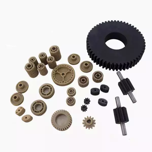
China Nylon PA66 Injection Molded Plastic Spur Gear with Good quality
Item Description
| Product Description | ||
| Merchandise | Identify | Nylon PA66 Injection Molded Plastic Spur Gear |
| Goods group | Injection plastic elements | |
| Substance | PP, Abs, Computer, Stomach muscles+Pc, Nylon, delrin (POM), PMMA, AS, PS, PE, PET, PVC, PEEK, and so forth GF added materials (Abs+GF, PA66+GF, PA666+GF) Rubber like content (TPE, PU, NBR, silicone, NBR+TPE etc) | |
| Dimension | All dimension and thickness obtainable. | |
| Form | capable of all styles as for each drawing | |
| Coloration | Natural,black,obvious (common obvious or high optical very clear), semi-clear, other colours (Pantone code or RAL code, or as for each client’s sample). | |
| Surface area finishing | Texture (VDI/MT normal, or made to client’s sample), polished (substantial polish, mirror polish), sleek, painting, powder coating, printing, electroplating etc. | |
| Drawing | Second or 3D draiwng in any image/photograph structure is Okay | |
| Cost-free sample | Indeed | |
| OEM/OEM | Of course | |
| Application | House, electronics, cars, machinery, medical center, cosmetics, Navy and Aerospace and many others. | |
| Top quality certification | ISO 90001:2008, TS16949, Fda, Achieve, ROHS, SGS | |
| QC | Each get generation will get much more than 10 occasions typical check and 5 fives moments random check out by our expert QC. Or by 3rd get together appointed by consumer | |
| Mildew | Molding Process | Injection molding, overmolding. |
| Mould kind | Injection plastic mould | |
| Regular | HASCO, DME, MISUMI, JIS, LKM, and so on. | |
| Tooling gear | Lathe,Milling,Grinder,Drill,CNC,EDM,Wire minimize machine,Punch machine | |
| Runner | Chilly or sizzling | |
| Gate | Facet Gate, Sub Gate, Direct Gate, Hook Gate, Pin Level Gate, and many others. | |
| Cavity | One or Multi cavities | |
| Mould Daily life | three hundred,000~1,00,000 times | |
HOW TO GET Solution/QUOTATION FOR YOUR PLASTIC Components:
| Order Answer | |
| Buy | OEM or ODM welcome. Cost-free sample or slab/button of content for your high quality evaluation, mildew sample in accordance with drawing for approval of mass manufacturing, |
| Payment conditions | L/C, T/T, WEST UNION, MONEYGRAM, PAYPAL, ESCROW |
| Lead time | three~5 months for mildew manufacturing, and 1~2 weeks for mass production |
| Package deal | As for each customer’s favour. Shock-absorbing baggage, Cartons, Wooden box, and picket or plastic pallet, |
| Shipping and delivery expression | FOB CHINA, CIF location port, DDP customer’s warehouse/address of merchandise |
| Cargo | By air mail, by sea, by convey like DHL, Fedex, UPS, TNT, EMS |
| Quality Control | Sample approval ahead of get, and QC check report(maybe by 3rd party) before harmony. |
Generation AND EQUIPMENTS:
| Equipment List | ||||
| Identify | SPECIFICATION | Manufacturer | Unique Place | Quantity |
| CNC Equipment | Graph 600 | KNUTH | GERMENY | three |
| 1370 | KAFO | ZheJiang | 25 | |
| EDM Equipment | ZNC450 | BHangZhouNA | ZheJiang | 3 |
| ZNC430 | BHangZhouNA | ZheJiang | 4 | |
| Grinding Equipment | ACC-350ST | BESFORD | CHINA | six |
| CNC Lathe Machining | L150G-II | OKUMA | CHINA | three |
| Wire Chopping Equipment | DK7732 | NEW Quickly | CHINA | three |
| Milling Device | SHCM-97A | GENTIGER | ZheJiang | 8 |
| Injection Equipment | 100T-450T | Haitian | CHINA | 12 |
| CMM Machine | CRT-PA574 | MITUTYO | JAPAN | one |
| Hardness Tester | TILO-T60 | MITUTYO | JAPAN | two |
|
US $0.01-0.1 / Piece | |
10 Pieces (Min. Order) |
###
| Material: | ABS |
|---|---|
| Application: | Medical, Household, Electronics, Automotive, Agricultural |
| Certification: | TS16949, RoHS |
| Color: | Black |
| OEM/ODM: | Welcomed |
| File: | Format Auto CAD, Pdf, JPG |
###
| Customization: |
Available
|
|---|
###
| Product Description | ||
| Products | Name | Nylon PA66 Injection Molded Plastic Spur Gear |
| Products category | Injection plastic parts | |
| Material | PP, ABS, PC, ABS+PC, Nylon, delrin (POM), PMMA, AS, PS, PE, PET, PVC, PEEK, etc; GF added material (ABS+GF, PA66+GF, PA666+GF); Rubber like material (TPE, PU, NBR, silicone, NBR+TPE etc) | |
| Size | All size and thickness available. | |
| Shape | capable of all shapes as per drawing | |
| Color | Natural,black,clear (standard clear or high optical clear), semi-transparent, other colors (Pantone code or RAL code, or as per client’s sample). | |
| Surface finishing | Texture (VDI/MT standard, or made to client’s sample), polished (high polish, mirror polish), smooth, painting, powder coating, printing, electroplating etc. | |
| Drawing | 2D or 3D draiwng in any image/picture format is OK | |
| Free sample | Yes | |
| OEM/OEM | Yes | |
| Application | Household, electronics, vehicles, machinery, hospital, cosmetics, Military and Aerospace etc. | |
| Quality certification | ISO 90001:2008, TS16949, FDA, REACH, ROHS, SGS | |
| QC | Every order production will get more than 10 times regular check and 5 fives times random check by our professional QC. Or by Third party appointed by customer | |
| Mold | Molding Process | Injection molding, overmolding. |
| Mould type | Injection plastic mould | |
| Standard | HASCO, DME, MISUMI, JIS, LKM, etc. | |
| Tooling equipment | Lathe,Milling,Grinder,Drill,CNC,EDM,Wire cut machine,Punch machine | |
| Runner | Cold or hot | |
| Gate | Side Gate, Sub Gate, Direct Gate, Hook Gate, Pin Point Gate, etc. | |
| Cavity | Single or Multi cavities | |
| Mould Life | 300,000~1,00,000 times | |
###
| Order Solution | |
| Order | OEM or ODM welcome. Free sample or slab/button of material for your quality evaluation, mold sample in accordance with drawing for approval of mass production, |
| Payment terms | L/C, T/T, WEST UNION, MONEYGRAM, PAYPAL, ESCROW |
| Lead time | 3~5 weeks for mold production, and 1~2 weeks for mass production |
| Package | As per customer’s favour. Shock-absorbing bags, Cartons, Wooden box, and wooden or plastic pallet, |
| Delivery term | FOB CHINA, CIF destination port, DDP customer’s warehouse/address of goods |
| Shipment | By air mail, by sea, by express like DHL, Fedex, UPS, TNT, EMS |
| Quality Control | Sample approval before order, and QC test report(maybe by third party) before balance. |
###
| EQUIPMENT LIST | ||||
| NAME | SPECIFICATION | BRAND | ORIGINAL PLACE | QUANTITY |
| CNC Machines | Graph 600 | KNUTH | GERMENY | 3 |
| 1370 | KAFO | TAIWAN | 25 | |
| EDM Machines | ZNC450 | BANDANA | TAIWAN | 3 |
| ZNC430 | BANDANA | TAIWAN | 4 | |
| Grinding Machines | ACC-350ST | BESFORD | CHINA | 6 |
| CNC Lathe Machining | L150G-II | OKUMA | CHINA | 3 |
| Wire Cutting Machines | DK7732 | NEW FAST | CHINA | 3 |
| Milling Machine | SHCM-97A | GENTIGER | TAIWAN | 8 |
| Injection Machine | 100T-450T | Haitian | CHINA | 12 |
| CMM Machine | CRT-PA574 | MITUTYO | JAPAN | 1 |
| Hardness Tester | TILO-T60 | MITUTYO | JAPAN | 2 |
|
US $0.01-0.1 / Piece | |
10 Pieces (Min. Order) |
###
| Material: | ABS |
|---|---|
| Application: | Medical, Household, Electronics, Automotive, Agricultural |
| Certification: | TS16949, RoHS |
| Color: | Black |
| OEM/ODM: | Welcomed |
| File: | Format Auto CAD, Pdf, JPG |
###
| Customization: |
Available
|
|---|
###
| Product Description | ||
| Products | Name | Nylon PA66 Injection Molded Plastic Spur Gear |
| Products category | Injection plastic parts | |
| Material | PP, ABS, PC, ABS+PC, Nylon, delrin (POM), PMMA, AS, PS, PE, PET, PVC, PEEK, etc; GF added material (ABS+GF, PA66+GF, PA666+GF); Rubber like material (TPE, PU, NBR, silicone, NBR+TPE etc) | |
| Size | All size and thickness available. | |
| Shape | capable of all shapes as per drawing | |
| Color | Natural,black,clear (standard clear or high optical clear), semi-transparent, other colors (Pantone code or RAL code, or as per client’s sample). | |
| Surface finishing | Texture (VDI/MT standard, or made to client’s sample), polished (high polish, mirror polish), smooth, painting, powder coating, printing, electroplating etc. | |
| Drawing | 2D or 3D draiwng in any image/picture format is OK | |
| Free sample | Yes | |
| OEM/OEM | Yes | |
| Application | Household, electronics, vehicles, machinery, hospital, cosmetics, Military and Aerospace etc. | |
| Quality certification | ISO 90001:2008, TS16949, FDA, REACH, ROHS, SGS | |
| QC | Every order production will get more than 10 times regular check and 5 fives times random check by our professional QC. Or by Third party appointed by customer | |
| Mold | Molding Process | Injection molding, overmolding. |
| Mould type | Injection plastic mould | |
| Standard | HASCO, DME, MISUMI, JIS, LKM, etc. | |
| Tooling equipment | Lathe,Milling,Grinder,Drill,CNC,EDM,Wire cut machine,Punch machine | |
| Runner | Cold or hot | |
| Gate | Side Gate, Sub Gate, Direct Gate, Hook Gate, Pin Point Gate, etc. | |
| Cavity | Single or Multi cavities | |
| Mould Life | 300,000~1,00,000 times | |
###
| Order Solution | |
| Order | OEM or ODM welcome. Free sample or slab/button of material for your quality evaluation, mold sample in accordance with drawing for approval of mass production, |
| Payment terms | L/C, T/T, WEST UNION, MONEYGRAM, PAYPAL, ESCROW |
| Lead time | 3~5 weeks for mold production, and 1~2 weeks for mass production |
| Package | As per customer’s favour. Shock-absorbing bags, Cartons, Wooden box, and wooden or plastic pallet, |
| Delivery term | FOB CHINA, CIF destination port, DDP customer’s warehouse/address of goods |
| Shipment | By air mail, by sea, by express like DHL, Fedex, UPS, TNT, EMS |
| Quality Control | Sample approval before order, and QC test report(maybe by third party) before balance. |
###
| EQUIPMENT LIST | ||||
| NAME | SPECIFICATION | BRAND | ORIGINAL PLACE | QUANTITY |
| CNC Machines | Graph 600 | KNUTH | GERMENY | 3 |
| 1370 | KAFO | TAIWAN | 25 | |
| EDM Machines | ZNC450 | BANDANA | TAIWAN | 3 |
| ZNC430 | BANDANA | TAIWAN | 4 | |
| Grinding Machines | ACC-350ST | BESFORD | CHINA | 6 |
| CNC Lathe Machining | L150G-II | OKUMA | CHINA | 3 |
| Wire Cutting Machines | DK7732 | NEW FAST | CHINA | 3 |
| Milling Machine | SHCM-97A | GENTIGER | TAIWAN | 8 |
| Injection Machine | 100T-450T | Haitian | CHINA | 12 |
| CMM Machine | CRT-PA574 | MITUTYO | JAPAN | 1 |
| Hardness Tester | TILO-T60 | MITUTYO | JAPAN | 2 |
What Is Injection Moulding?
Injection molding is a process of producing precision-molded parts by fusing raw plastics and guiding them into a mold. The main components of an injection mold are a hopper, barrel, and reciprocating screw. Before injection, the raw plastics are mixed with coloring pigments and reinforcing additives.
Characteristics of injection molded parts
 Injection molding is the process of manufacturing plastic parts. It uses thermoplastic, thermoset, or elastomers to manufacture components. The range of materials is enormous and includes tens of thousands of different polymers. They are blended with other materials and alloys to produce a wide range of properties. Designers select the appropriate materials for the job based on the properties and functions desired in the finished part. During the mold design process, mold materials must be carefully chosen, as different materials require different molding parameters.
Injection molding requires precise tolerances of the temperature and strain levels. The maximum strain level is about 0.15 percent. It is possible to adjust these parameters to meet the requirements of an injection molding project. The resulting products can be easily checked for quality by measuring the strain and temperature of the mold inserts in real time.
Injection molding is known for its laminar flow of the polymer. However, there is still a possibility for side-to-side thermal variations in the part forming cavity. This is illustrated in FIG. 4. The part has high and low sheared areas; the higher sheared areas flow on the bottom side of the part, while the lower sheared areas flow on the top side.
Injection molding is used to make many different types of plastic parts, from small parts to entire body panels of a car. These parts can be made from a variety of different materials, such as polypropylene for toys and ABS for consumer electronics. They can also be made from metal, such as aluminum or steel.
The melting temperature of plastic parts must be appropriate for the project’s specifications. The mold should be large enough to produce the parts desired. This will minimize the impact of uneven shrinkage on the product’s dimensional accuracy. In addition to the temperature, a mold must be designed with the material’s properties in mind.
Tooling fabrication
Injection molded parts are produced using molds. This process is a complex process that requires customization to ensure proper fit and function. The main component of a mold is the base, which holds the cavities, ejectors and cooling lines. The size and position of these components are crucial to the production of quality parts. Incorrectly sized vents can cause trapped air to enter the part during the molding process. This can lead to gas bubbles, burn marks, and poor part quality.
The material used for tooling fabrication is usually H-13 tool steel. This steel is suitable for injection molded parts as it has a low elongation value. The material used to fabricate tooling for injection molded parts typically has a high yield strength. The material used for injection moulding tooling is typically 420 stainless steel or H-13 tool steel. These materials are suitable for most injection molding processes and have comparable yield strength compared to wrought or MIM parts.
Another important part of tooling fabrication is the design of the mold. It is important to design the mold with a draft angle, as this will make ejection easier and reduce costs. A draft angle of 5o is recommended when designing a tall feature. Choosing a draft angle is essential to ensuring that the plastic part is free from air bubbles after injection molding.
Injection moulding tooling costs can account for as much as 15% of the cost of an injection moulded part. With innovation in mould materials and design, tooling fabrication can be more efficient and cost-effective.
Surface finishes on injection molded parts
Surface finishes on injection molded parts can have a variety of effects on the part’s appearance and performance. Different materials lend themselves to different kinds of surface finishes, with some plastics better suited for smooth, glossy finishes than others. The type of surface finish is also affected by several factors, including the speed of injection and the melt temperature. Faster injection speeds help improve the quality of plastic finishes by decreasing the visibility of weld lines and improving the overall appearance of the parts.
For a smooth plastic surface finish, some companies require a high level of roughness on the part. Others may prefer a more rough look, but both options can have their benefits. The type of surface finish chosen will depend on the part’s purpose and intended application. For example, a glossy plastic finish may be preferred for a cosmetic part, while a rougher finish may be better suited for a mechanical part that must be tough and cost-effective.
Surface finishes on injection molded parts are often customized to match the application. For example, some parts require a rough surface finish because they require a greater amount of friction. These parts may require a sandblasting process to achieve the desired texture. Other processes can also be used to control plastic texture.
The type of surface finish depends on the materials used, as well as the design and shape of the part. The type of material used, additives, and temperature also have an impact on the surface finish. It is also important to consider surface finishes early in the design process.
Importance of a secondary operation to improve accuracy
While most injection molded parts do not require secondary operations, some components do require this type of processing. The surface finish of a component will determine how well it functions and what other secondary operations are necessary. Depending on the part’s function, a smooth or textured surface may be appropriate. Additionally, some parts may require surface preparation before applying adhesives, so an accurate surface finish can make all the difference. In order to achieve the desired finish, the injection molder should have experience molding different materials. He or she should also have the knowledge of how to simulate the flow of a mold. Also, experienced molders know how to mix materials to achieve the desired color, avoiding the need for secondary painting processes.
Injection molding is a complex process that requires precision and accuracy. The optimal temperature of the melted plastic must be chosen, as well as the mold itself. The mold must also be designed for the correct flow of plastic. In addition, it must be made of the best thermoplastic material for the part’s design. Finally, the correct time must be allowed for the part to be solid before it is ejected. Many of these issues can be overcome with specialized tooling that is customized to the part’s design.
Injection molding offers the opportunity to make complex parts at low cost. It also allows manufacturers to make parts with complicated geometries and multiple functions.
editor by czh 2023-01-06
China high quality High Quality Plastic Butterfly Valve Lever PVC Wafer Type Worm Gear Flanged Butterfly Valve UPVC Manual Handle Butterfly Valve Level DIN ANSI JIS Standard with Good quality
Solution Description
Higher High quality
Plastic Butterfly Valve Lever
PVC Wafer Kind Worm Gear Flanged Butterfly Valve
UPVC Manual Deal with Butterfly Valve Stage
DIN ANSI JIS Standard
DN50-DN400 ( 2″-16″ )
Large High quality
Plastic Butterfly Valve
PVC Wafer Kind Butterfly Valve
UPVC Manage Butterfly Valve Stage
DIN ANSI JIS Standard
DN50-DN400 ( 2″-sixteen” )
Feature:
With Carbon Steel Stem #45. Disc with PVC. Seat & O-Ring with EPDM Rubber.
With Stainless Metal Stem # 304. Disc with PVC. Seat & O-Ring with EPDM Rubber
With Stainless Steel Stem # 316. Disc with PVC. Seat & O-Ring with EPDM Rubber
With Stainless Metal Stem # 304. Disc with PVC. Seat & O-Ring with FPM Rubber
With Stainless Metal Stem #316. Disc with PVC Seat & O-Ring with FPM Rubber
PVC Butterfly Valve for Water Supply DIN ANSI JIS Standard
DN.50mm to DN.400mm
Attributes
Water Supply
Material : PVC-U
Standard : DIN ANSI JIS Regular
Connection : Flange
SIZE : DN50 ( 63mm ) 2″ ~ DN400 (400mm ) sixteen”
Working Pressure : 150PSI 1.0 MPa
100PSI 0.6MPa
Color : Dark Gray
PVC Butterfly Valve ( Level & Equipment )
FRPP Butterfly Valve ( Degree & Gear )
PVC Non Actuator Butterfly Valve for Electrical & Pneumatic Actuator Usage
PVC-U FRPP Butterfly Valve for Electrical & Pneumatic Actuator Utilization
DN50-DN400 ( 2″- 16” )
DN50 – DN150 (2″- 6″) 100PSI PN0.8MPa
DN200-DN300 (8″- 12″) 80PSI PN0.5MPa
DN350-DN400 (fourteen”- sixteen”) 60PSI PN0.4MPa
Regular: DIN, ANSI, JIS Regular
Hello-High quality Low Torque Acid-Evidence Alkali-Proof 100% Test
Can be Personalized
Distinct Sizes Shaft of Sq., Oblate, Round Keyway
Heavy the Valve Body, Thicken the Valve Plate
Thicken the Valve Stem, the Valve Stem Limit
With Carbon Metal Stem #45 & EPDM Rubber
With Stainless Metal Stem #304 & EPDM / FPM Rubber
With Stainless Steel Stem #316 & EPDM / FPM Rubber
Integrated Composition of Valve Seat and Valve Entire body
Actuator Mounting Gap
with ISO5211 Standard Without Bracket, Direct Connection
PVC-U FRPP Butterfly Valve ( Lever Kind ) DN50-DN200 ( 2″- 8″ )
Working Stress:
DN50-DN150 ( 2″- 6″ ) 150PSI PN1.0MPa
DN200 ( 8″ ) 90PSI PN0.6MPa
Common: DIN, ANSI, JIS Common
Hi-High quality, Lower Torque, Lockable, Acid-Proof, Alkali-Proof, 100% Take a look at
PVC Butterfly Valve Patent Technologies
Increase the Locking Gap to Lock the Valve
Built-in Structure of Valve Seat and Valve Body.
Weighty the Valve Entire body, Thicken the Valve Plate
Thicken the Valve Stem, the Valve Stem Restrict
With Carbon Metal Stem #45 & EPDM Rubber
With Stainless Metal Stem #304 & EPDM / FPM Rubber
With Stainless Steel Stem #316 & EPDM / FPM Rubber
For a longer time & Wider Deal with,Take care of Lever Greater, Energy Operation
PVC-U FRPP Butterfly Valve ( Gear Variety ) DN50-DN400 ( 2″- sixteen” )
DN50-DN200 (2″- 8″) 150PSI PN1.0MPa
DN250-DN300 (10″- 12″) 90PSI PN0.6MPa
DN350-DN400 (14″- 16″) 60PSI PN0.4MPa
Standard: DIN, ANSI, JIS Common
Hello-Good quality Low Torque Acid-Evidence Alkali-Proof 100% Check
Hygienic Level PVC Raw Materials Injection
Gear Box and Hand Wheel Can Be Produced of Plastic
Built-in Framework of Valve Seat and Valve Entire body
With Carbon Steel Stem #forty five & EPDM Rubber
With Stainless Steel Stem #304 & EPDM / FPM Rubber
With Stainless Metal Stem #316 & EPDM / FPM Rubber
How to Pick the Correct Worm Shaft
You may possibly be curious to know how to pick the correct Worm Shaft. In this write-up, you will understand about worm modules with the very same pitch diameter, Double-thread worm gears, and Self-locking worm generate. After you have decided on the appropriate Worm Shaft, you will uncover it less complicated to use the tools in your home. There are numerous rewards to deciding on the appropriate Worm Shaft. Study on to find out much more.
Concave shape
The concave form of a worm’s shaft is an important characteristic for the design and style of a worm gearing. Worm gearings can be found in a broad variety of designs, and the simple profile parameters are offered in professional and firm literature. These parameters are employed in geometry calculations, and a selection of the right worm gearing for a distinct software can be primarily based on these needs.
The thread profile of a worm is outlined by the tangent to the axis of its major cylinder. The tooth are formed in a straight line with a somewhat concave form together the sides. It resembles a helical equipment, and the profile of the worm alone is straight. This kind of gearing is frequently employed when the quantity of tooth is greater than a specified limit.
The geometry of a worm gear relies upon on the type and company. In the earliest times, worms ended up manufactured comparable to basic screw threads, and could be chased on a lathe. For the duration of this time, the worm was usually made with straight-sided resources to make threads in the acme airplane. Later, grinding tactics improved the thread complete and decreased distortions resulting from hardening.
When a worm gearing has multiple teeth, the pitch angle is a key parameter. A greater pitch angle increases efficiency. If you want to increase the pitch angle with no rising the quantity of teeth, you can change a worm pair with a diverse number of thread commences. The helix angle have to boost while the center distance continues to be continual. A larger pitch angle, however, is nearly never employed for electricity transmissions.
The least quantity of equipment tooth depends on the angle of strain at zero gearing correction. The diameter of the worm is d1, and is primarily based on a known module price, mx or mn. Typically, greater values of m are assigned to bigger modules. And a smaller amount of teeth is referred to as a low pitch angle. In situation of a lower pitch angle, spiral gearing is used. The pitch angle of the worm equipment is smaller sized than 10 degrees.
Several-thread worms
Multi-thread worms can be divided into sets of 1, two, or four threads. The ratio is decided by the number of threads on each and every established and the number of teeth on the apparatus. The most typical worm thread counts are 1,2,4, and 6. To uncover out how a lot of threads you have, count the commence and finish of each thread and divide by two. Making use of this approach, you will get the right thread depend every time.
The tangent aircraft of a worm’s pitch profile changes as the worm moves lengthwise alongside the thread. The direct angle is greatest at the throat, and decreases on both sides. The curvature radius r” may differ proportionally with the worm’s radius, or pitch angle at the considered point. That’s why, the worm sales opportunities angle, r, is increased with decreased inclination and decreases with rising inclination.
Multi-thread worms are characterized by a continual leverage among the gear surface and the worm threads. The ratio of worm-tooth surfaces to the worm’s duration may differ, which enables the wormgear to be adjusted in the same route. To optimize the gear contact in between the worm and equipment, the tangent partnership among the two surfaces is optimum.
The effectiveness of worm gear drives is largely dependent on the helix angle of the worm. A number of thread worms can improve the efficiency of the worm gear generate by as considerably as 25 to 50% in contrast to one-thread worms. Worm gears are produced of bronze, which reduces friction and warmth on the worm’s tooth. A specialised device can lower the worm gears for optimum efficiency.
Double-thread worm gears
In several different programs, worm gears are utilised to drive a worm wheel. These gears are special in that the worm are not able to be reversed by the electrical power applied to the worm wheel. Because of their self-locking houses, they can be utilised to prevent reversing motion, though this is not a trustworthy purpose. Purposes for worm gears include hoisting products, elevators, chain blocks, fishing reels, and automotive electricity steering. Due to the fact of their compact size, these gears are usually used in applications with restricted space.
Worm sets normally show more wear than other kinds of gears, and this means that they require far more minimal contact designs in new areas. Worm wheel tooth are concave, producing it challenging to measure tooth thickness with pins, balls, and gear tooth calipers. To evaluate tooth thickness, nonetheless, you can evaluate backlash, a measurement of the spacing between tooth in a gear. Backlash can differ from one worm equipment to one more, so it is crucial to examine the backlash at several details. If the backlash is different in two places, this indicates that the enamel could have different spacing.
One-thread worm gears give large pace reduction but reduced performance. A multi-thread worm equipment can provide large performance and higher pace, but this comes with a trade-off in phrases of horsepower. Even so, there are numerous other applications for worm gears. In addition to heavy-duty programs, they are frequently employed in mild-responsibility gearboxes for a range of features. When employed in conjunction with double-thread worms, they let for a considerable velocity reduction in one particular step.
Stainless-steel worm gears can be used in damp environments. The worm equipment is not inclined to rust and is perfect for moist and moist environments. The worm wheel’s smooth surfaces make cleaning them easy. However, they do demand lubricants. The most widespread lubricant for worm gears is mineral oil. This lubricant is designed to safeguard the worm drive.
Self-locking worm travel
A self-locking worm push helps prevent the platform from shifting backward when the motor stops. A dynamic self-locking worm travel is also possible but does not include a keeping brake. This type of self-locking worm push is not prone to vibrations, but might rattle if introduced. In addition, it might call for an added brake to keep the system from shifting. A constructive brake might be needed for security.
A self-locking worm push does not enable for the interchangeability of the driven and driving gears. This is not like spur equipment trains that enable both to interchange positions. In a self-locking worm travel, the driving gear is always engaged and the pushed gear stays stationary. The push system locks immediately when the worm is operated in the incorrect manner. Several sources of information on self-locking worm gears contain the Machinery’s Handbook.
A self-locking worm generate is not tough to create and has a fantastic mechanical advantage. In reality, the output of a self-locking worm push cannot be backdriven by the enter shaft. DIYers can create a self-locking worm drive by modifying threaded rods and off-the-shelf gears. Even so, it is simpler to make a ratchet and pawl system, and is considerably significantly less costly. Nonetheless, it is essential to realize that you can only drive one particular worm at a time.
One more gain of a self-locking worm travel is the fact that it is not attainable to interchange the input and output shafts. This is a major benefit of using such a mechanism, as you can attain substantial equipment reduction with no increasing the size of the gear box. If you are considering about purchasing a self-locking worm gear for a particular software, take into account the following guidelines to make the appropriate option.
An enveloping worm equipment set is ideal for apps demanding substantial accuracy and performance, and minimum backlash. Its tooth are formed otherwise, and the worm’s threads are modified to boost surface speak to. They are a lot more pricey to manufacture than their one-start off counterparts, but this sort is greatest for purposes exactly where accuracy is crucial. The worm push is also a great selection for weighty vehicles since of their large dimensions and large-torque ability.


China supplier New Design Industrial Gear Transmission RV Worm Speed Reducer (Size 030-150) wholesaler
Item Description
Merchandise Description
Company Profile
In 2571, HangZhou CZPT Equipment Co.,ltd was recognized by Ms. Iris and her 2 companions(Mr. Tian and Mr. Yang) in HangZhou city(ZHangZhoug province, China), all 3 Founders are engineers who have more than averaged thirty several years of knowledge. Then because the needs of company enlargement, in 2014, it moved to the existing Xihu (West Lake) Dis. Industrial Zone (HangZhou city, ZHangZhoug province, China).
By way of our effectively-known model ND, CZPT Machinery delivers agricultural remedies to agriculture machinery maker and distributors globally by way of a total line of spiral bevel gearboxes, straight bevel gearboxes, spur gearboxes, push shafts, sheet metallic, hydraulic cylinder, motors, tyre, worm gearboxes, worm operators etc. Merchandise can be customized as ask for.
We, CZPT machinery proven a total good quality administration program and sales support community to provide clientele with higher-quality items and satisfactory provider. Our products are offered in 40 provinces and municipalities in China and 36 countries and areas in the planet, our principal market is the European industry.
Our factory
Our sample area
Certifications
Why select us?
one) Customization: With a robust R&D staff, and we can produce products as needed. It only normally takes up to 7 days for us to design a established of drawings. The manufacturing time for new merchandise is usually fifty days or considerably less.
2) Top quality: We have our very own complete inspection and testing tools, which can guarantee the quality of the products.
3) Ability: Our once-a-year generation ability is above 500,000 sets, also, we also take little amount orders, to satisfy the requirements of distinct customer’s acquire quantities.
four) Services: We emphasis on supplying higher-quality goods. Our items are in line with international expectations and are mainly exported to Europe, Australia, and other international locations and locations.
5) Cargo: We are near to HangZhou and ZheJiang ports, to supply the fastest shipping service.
Packaging & Shipping and delivery
FAQ
Q: Are you a trading firm or maker?
A: We are factory and supplying gearbox ODM & OEM solutions for the European marketplace for more than 10 years
Q: Do you provide samples? is it free of charge or added?
A: Sure, we could offer the sample for free charge but do not shell out the price of freight.
Q: How extended is your shipping time? What is your phrases of payment?
A: Typically it is 40-45 days. The time might range relying on the solution and the level of customization.
For regular merchandise, the payment is: 30% T/T in advance,balance prior to cargo.
Q: What is the actual MOQ or price tag for your merchandise?
A: As an OEM business, we can give and adapt our merchandise to a broad range of wants.
Hence, MOQ and cost might significantly fluctuate with dimension, materials and further technical specs For instance, high priced goods or regular goods will usually have a decrease MOQ. Please make contact with us with all relevant specifics to get the most accurate quotation.
If you have another concern, please truly feel free to get in touch with us.
Worm Shafts and Gearboxes
If you have a gearbox, you could be wondering what the best Worm Shaft is for your software. There are numerous factors to consider, such as the Concave form, Quantity of threads, and Lubrication. This article will describe each issue and aid you choose the proper Worm Shaft for your gearbox. There are numerous options accessible on the marketplace, so will not be reluctant to store all around. If you are new to the globe of gearboxes, go through on to discover far more about this well-known variety of gearbox.
Concave condition
The geometry of a worm equipment differs considerably depending on its company and its supposed use. Early worms experienced a standard profile that resembled a screw thread and could be chased on a lathe. Later on, resources with a straight sided g-angle have been developed to generate threads that were parallel to the worm’s axis. Grinding was also designed to boost the end of worm threads and lessen distortions that happen with hardening.
To choose a worm with the appropriate geometry, the diameter of the worm equipment must be in the very same unit as the worm’s shaft. After the standard profile of the worm equipment is identified, the worm equipment enamel can be specified. The calculation also includes an angle for the worm shaft to prevent it from overheating. The angle of the worm shaft ought to be as near to the vertical axis as attainable.
Double-enveloping worm gears, on the other hand, do not have a throat around the worm. They are helical gears with a straight worm shaft. Because the teeth of the worm are in contact with each other, they produce significant friction. Not like double-enveloping worm gears, non-throated worm gears are more compact and can manage more compact masses. They are also straightforward to manufacture.
The worm gears of distinct companies offer many rewards. For occasion, worm gears are a single of the most successful approaches to enhance torque, whilst lower-good quality supplies like bronze are tough to lubricate. Worm gears also have a minimal failure rate simply because they permit for appreciable leeway in the design approach. Even with the variances amongst the two specifications, the total efficiency of a worm equipment technique is the exact same.
The cone-formed worm is one more sort. This is a technological plan that brings together a straight worm shaft with a concave arc. The concave arc is also a valuable utility design. Worms with this condition have a lot more than three contacts at the identical time, which indicates they can lessen a massive diameter without excessive use. It is also a reasonably lower-cost model.
Thread pattern
A great worm gear demands a perfect thread sample. There are a couple of key parameters that establish how great a thread sample is. Firstly, the threading pattern need to be ACME-threaded. If this is not feasible, the thread must be created with straight sides. Then, the linear pitch of the “worm” have to be the identical as the round pitch of the corresponding worm wheel. In straightforward phrases, this means the pitch of the “worm” is the very same as the round pitch of the worm wheel. A quick-alter gearbox is normally used with this type of worm gear. Alternatively, lead-screw change gears are employed rather of a swift-modify gear box. The pitch of a worm gear equals the helix angle of a screw.
A worm gear’s axial pitch must match the round pitch of a gear with a larger axial pitch. The round pitch is the distance among the details of tooth on the worm, whilst the axial pitch is the length amongst the worm’s teeth. Another issue is the worm’s lead angle. The angle amongst the pitch cylinder and worm shaft is called its guide angle, and the higher the lead angle, the greater the efficiency of a equipment.
Worm equipment tooth geometry may differ based on the maker and intended use. In early worms, threading resembled the thread on a screw, and was very easily chased using a lathe. Afterwards, grinding enhanced worm thread finishes and minimized distortions from hardening. As a outcome, today, most worm gears have a thread pattern corresponding to their dimensions. When selecting a worm gear, make positive to check for the number of threads just before acquiring it.
A worm gear’s threading is vital in its procedure. Worm enamel are typically cylindrical, and are arranged in a pattern similar to screw or nut threads. Worm teeth are usually shaped on an axis of perpendicular in comparison to their parallel counterparts. Because of this, they have greater torque than their spur equipment counterparts. Moreover, the gearing has a reduced output velocity and substantial torque.
Quantity of threads
Distinct varieties of worm gears use distinct figures of threads on their planetary gears. A single threaded worm gear need to not be utilised with a double-threaded worm. A one-threaded worm equipment ought to be employed with a one-threaded worm. One-threaded worms are far more efficient for pace reduction than double-threaded ones.
The number of threads on a worm’s shaft is a ratio that compares the pitch diameter and number of teeth. In general, worms have 1,2,4 threads, but some have a few, five, or six. Counting thread starts can support you decide the amount of threads on a worm. A solitary-threaded worm has less threads than a a number of-threaded worm, but a multi-threaded worm will have more threads than a mono-threaded planetary gear.
To evaluate the quantity of threads on a worm shaft, a tiny fixture with two ground faces is utilized. The worm need to be removed from its housing so that the completed thread spot can be inspected. Soon after determining the quantity of threads, simple measurements of the worm’s exterior diameter and thread depth are taken. After the worm has been accounted for, a solid of the tooth room is manufactured using epoxy materials. The casting is moulded among the two tooth flanks. The V-block fixture rests towards the outdoors diameter of the worm.
The circular pitch of a worm and its axial pitch must match the round pitch of a bigger equipment. The axial pitch of a worm is the distance in between the points of the tooth on a worm’s pitch diameter. The lead of a thread is the length a thread travels in 1 revolution. The guide angle is the tangent to the helix of a thread on a cylinder.
The worm gear’s pace transmission ratio is dependent on the quantity of threads. A worm equipment with a higher ratio can be simply reduced in one particular phase by employing a set of worm gears. Nevertheless, a multi-thread worm will have much more than two threads. The worm gear is also a lot more efficient than single-threaded gears. And a worm equipment with a high ratio will enable the motor to be utilised in a assortment of programs.
Lubrication
The lubrication of a worm equipment is notably demanding, thanks to its friction and higher sliding make contact with pressure. Fortunately, there are a number of possibilities for lubricants, such as compounded oils. Compounded oils are mineral-dependent lubricants formulated with 10 p.c or much more fatty acid, rust and oxidation inhibitors, and other additives. This mix outcomes in enhanced lubricity, lowered friction, and decrease sliding put on.
When deciding on a lubricant for a worm shaft, make sure the product’s viscosity is correct for the sort of gearing utilized. A reduced viscosity will make the gearbox difficult to actuate and rotate. Worm gears also endure a greater sliding motion than rolling movement, so grease should be in a position to migrate evenly all through the gearbox. Recurring sliding motions will drive the grease away from the contact zone.
One more thing to consider is the backlash of the gears. Worm gears have higher equipment ratios, occasionally 300:1. This is crucial for power applications, but is at the identical time inefficient. Worm gears can make heat throughout the sliding motion, so a substantial-quality lubricant is vital. This type of lubricant will decrease heat and make sure optimum performance. The pursuing suggestions will assist you decide on the proper lubricant for your worm gear.
In minimal-pace applications, a grease lubricant might be adequate. In greater-velocity applications, it truly is greatest to implement a artificial lubricant to stop premature failure and tooth dress in. In both situations, lubricant option relies upon on the tangential and rotational speed. It is essential to follow manufacturer’s guidelines concerning the selection of lubricant. But don’t forget that lubricant selection is not an straightforward job.
China factory 12mm 90 Degree 5 Volt 12 Volt Mini Gear Motor with Worm Gearbox for Electrical Door Lock near me factory
Product Description
12mm ninety degree 5 volt twelve volt mini gear motor with worm gearbox for electrical door lock
1. Gearbox Data
two. Gear Motor Knowledge
Note: It is the normal specification for reference only, We can choose DC motor with diverse voltage pace to meet up with your torque and speed prerequisite.
three. Mechanical Dimension
Company Profile
one. About us
Main Goods: 1) DC Brush motor: six-130mm diameter, .01-1000W output energy
2) DC Spur Gear Motor: 12-110mm diameter, .1-300W output power
3) DC Planeary Equipment Motor: ten-82mm diameter, .1-100W output power
4) Brushless DC Motor: 28-110mm, 5-1500W output power
5) Stepper Motor: NEMA 08 to NEMA forty three, Can with gearbox and direct screw
6) Servo Motor: 42mm to 130mm diameter, 50-4000w
7) AC Gear Motor: 49 to 100mm diameter, 6-one hundred forty output power
2. Creation
Creation line
Packing&Shipping and delivery
Certifications
Client Visits
FAQ
Q: What’s your main items?
A:We presently generate Brushed Dc Motors, Brushed Dc equipment Motors, Planetary Dc Gear Motors, Brushless Dc Motors, Stepper motors and Ac Motors and so on. You can examine the requirements for over motors on our website and you can electronic mail us to suggest required motors per your specification as well.
Q:How to pick a appropriate motor?
A:If you have motor photographs or drawings to present us, or you have detailed specs like voltage, velocity, torque, motor size, doing work method of the motor, required existence time and sound degree and so forth, make sure you do not be reluctant to let us know, then we can recommend suited motor for every your ask for accordingly.
Q: Do you have customized services for your normal motors?
A:Of course, we can customize per your request for the voltage, pace, torque and shaft dimension/condition. If you need added wires/cables soldered on the terminal or require to add connectors, or capacitors or EMC we can make it as well.
Q: you have individual design services for motors?
A:Of course, we would like to layout motors separately for our customers, but it may need some CZPT demand and design and style cost.
Q:Can I have samples for screening 1st?
A:Of course, undoubtedly you can. After confirmed the needed motor specs, we will estimate and supply a proforma invoice for samples, as soon as we get the payment, we will get a Go from our account department to move forward samples appropriately.
Q:How do you make positive motor top quality?
A:We have our personal inspection procedures: for incoming materials, we have signed sample and drawing to make positive qualified incoming resources for production process, we have tour inspection in the approach and ultimate inspection to make confident experienced merchandise ahead of transport.
Q:What is your lead time?
A:Usually talking, our standard common product will need to have 25-30days, a bit lengthier for tailored items. But we are very adaptable on the direct time, it will relies upon on the distinct orders
Q:What is your payment expression?
A:For all our new buyers, we will need 40% deposite, 60% paid just before cargo.
Q:When will you reply following obtained my inquiries?
A:We will reaction in 24 several hours as soon as get your inquires.
Q:How can I CZPT you to make sure my income is secure?
A:We are qualified by the 3rd social gathering SGS and we have exported to in excess of 85 international locations up to June.2017. You can verify our reputation with our existing customers in your nation (if our consumers do not mind), or you can get via alibaba to get trade assurance from alibaba to make sure your money is protected.
Q:What’s the least purchase amount?
A:Our minimal get quantity depends on different motor models, you should e mail us to check out. Also, we normally do not settle for personalized use motor orders.
Q:What is actually your transport strategy for motors?
A:For samples and deals considerably less than 100kg, we generally advise convey transport For weighty packages, we generally propose air transport or sea delivery. But it all relies upon on our customers’ wants.
Q:What certifications do you have?
A:We at the moment have CE and ROSH certifications.
Q:Can you send me your price tag listing?
A:Given that we have hundreds of various merchandise, and value varies for every different specifications, we are not CZPT to provide a price record. But we can quotation inside 24 hrs when got your inquirues to make certain you can get the value in time.
Q:Can I go to your company?
A:Yes, welcome to go to our company, but you should enable us know at least 2 weeks in advance to aid us make certain no other meetings for the duration of the day you visit us. Many thanks!
Calculating the Deflection of a Worm Shaft
In this post, we are going to examine how to determine the deflection of a worm gear’s worm shaft. We’ll also discuss the qualities of a worm equipment, such as its tooth forces. And we will cover the crucial traits of a worm gear. Go through on to discover far more! Below are some factors to think about before buying a worm equipment. We hope you take pleasure in understanding! Following looking through this article, you are going to be properly-geared up to pick a worm equipment to match your demands.
Calculation of worm shaft deflection
The main objective of the calculations is to figure out the deflection of a worm. Worms are utilised to switch gears and mechanical gadgets. This sort of transmission uses a worm. The worm diameter and the variety of teeth are inputted into the calculation steadily. Then, a desk with proper options is shown on the screen. Soon after finishing the table, you can then shift on to the major calculation. You can modify the toughness parameters as well.
The optimum worm shaft deflection is calculated using the finite aspect strategy (FEM). The product has numerous parameters, like the dimension of the elements and boundary problems. The results from these simulations are when compared to the corresponding analytical values to calculate the highest deflection. The outcome is a table that shows the highest worm shaft deflection. The tables can be downloaded below. You can also locate far more data about the diverse deflection formulation and their purposes.
The calculation method utilised by DIN EN 10084 is based mostly on the hardened cemented worm of 16MnCr5. Then, you can use DIN EN 10084 (CuSn12Ni2-C-GZ) and DIN EN 1982 (CuAl10Fe5Ne5-C-GZ). Then, you can enter the worm face width, possibly manually or using the car-suggest choice.
Widespread approaches for the calculation of worm shaft deflection offer a great approximation of deflection but do not account for geometric modifications on the worm. While Norgauer’s 2021 technique addresses these problems, it fails to account for the helical winding of the worm tooth and overestimates the stiffening impact of gearing. Much more refined approaches are needed for the productive design and style of slim worm shafts.
Worm gears have a minimal sound and vibration when compared to other varieties of mechanical products. Even so, worm gears are usually restricted by the volume of use that takes place on the softer worm wheel. Worm shaft deflection is a important influencing element for sounds and put on. The calculation method for worm gear deflection is available in ISO/TR 14521, DIN 3996, and AGMA 6022.
The worm equipment can be made with a precise transmission ratio. The calculation requires dividing the transmission ratio in between more stages in a gearbox. Energy transmission input parameters have an effect on the gearing properties, as nicely as the content of the worm/equipment. To achieve a far better effectiveness, the worm/equipment material need to match the circumstances that are to be knowledgeable. The worm gear can be a self-locking transmission.
The worm gearbox contains many machine aspects. The principal contributors to the overall energy loss are the axial masses and bearing losses on the worm shaft. Therefore, diverse bearing configurations are studied. A single type contains finding/non-locating bearing preparations. The other is tapered roller bearings. The worm equipment drives are considered when finding versus non-finding bearings. The analysis of worm gear drives is also an investigation of the X-arrangement and 4-stage contact bearings.
Influence of tooth forces on bending stiffness of a worm gear
The bending stiffness of a worm equipment is dependent on tooth forces. Tooth forces boost as the electrical power density boosts, but this also qualified prospects to improved worm shaft deflection. The ensuing deflection can influence performance, use load ability, and NVH actions. Continuous advancements in bronze components, lubricants, and manufacturing quality have enabled worm gear manufacturers to generate more and more high power densities.
Standardized calculation strategies just take into account the supporting effect of the toothing on the worm shaft. Even so, overhung worm gears are not included in the calculation. In addition, the toothing region is not taken into account unless of course the shaft is created up coming to the worm gear. In the same way, the root diameter is treated as the equal bending diameter, but this ignores the supporting result of the worm toothing.
A generalized formula is presented to estimate the STE contribution to vibratory excitation. The outcomes are applicable to any gear with a meshing pattern. It is advisable that engineers examination various meshing approaches to receive much more correct outcomes. One way to check tooth-meshing surfaces is to use a finite aspect stress and mesh subprogram. This computer software will measure tooth-bending stresses below dynamic loads.
The effect of tooth-brushing and lubricant on bending stiffness can be achieved by increasing the pressure angle of the worm pair. This can lessen tooth bending stresses in the worm equipment. A additional method is to insert a load-loaded tooth-contact examination (CCTA). This is also used to evaluate mismatched ZC1 worm drive. The final results attained with the approach have been broadly used to numerous varieties of gearing.
In this research, we identified that the ring gear’s bending stiffness is extremely influenced by the enamel. The chamfered root of the ring equipment is bigger than the slot width. Hence, the ring gear’s bending stiffness may differ with its tooth width, which boosts with the ring wall thickness. Furthermore, a variation in the ring wall thickness of the worm equipment brings about a increased deviation from the design and style specification.
To comprehend the impact of the teeth on the bending stiffness of a worm equipment, it is critical to know the root condition. Involute tooth are vulnerable to bending stress and can crack below intense conditions. A tooth-breakage examination can management this by identifying the root condition and the bending stiffness. The optimization of the root condition right on the final equipment minimizes the bending stress in the involute enamel.
The impact of tooth forces on the bending stiffness of a worm gear was investigated making use of the CZPT Spiral Bevel Equipment Check Facility. In this review, multiple tooth of a spiral bevel pinion ended up instrumented with strain gages and examined at speeds ranging from static to 14400 RPM. The checks have been carried out with power ranges as substantial as 540 kW. The outcomes obtained ended up in contrast with the evaluation of a three-dimensional finite factor model.
Attributes of worm gears
Worm gears are unique kinds of gears. They characteristic a variety of qualities and apps. This write-up will examine the characteristics and positive aspects of worm gears. Then, we will look at the frequent applications of worm gears. Let’s take a appear! Prior to we dive in to worm gears, let’s overview their abilities. Hopefully, you will see how versatile these gears are.
A worm gear can obtain substantial reduction ratios with little hard work. By including circumference to the wheel, the worm can tremendously enhance its torque and reduce its velocity. Typical gearsets need multiple reductions to achieve the very same reduction ratio. Worm gears have less relocating areas, so there are less locations for failure. Nonetheless, they can’t reverse the direction of energy. This is due to the fact the friction in between the worm and wheel makes it impossible to transfer the worm backwards.
Worm gears are commonly utilized in elevators, hoists, and lifts. They are particularly valuable in applications in which halting speed is critical. They can be incorporated with smaller sized brakes to make sure security, but should not be relied on as a major braking technique. Typically, they are self-locking, so they are a good option for many apps. They also have numerous benefits, which includes elevated performance and security.
Worm gears are created to attain a specific reduction ratio. They are typically arranged among the input and output shafts of a motor and a load. The two shafts are typically positioned at an angle that guarantees suitable alignment. Worm gear gears have a heart spacing of a body size. The middle spacing of the equipment and worm shaft decides the axial pitch. For occasion, if the gearsets are set at a radial distance, a smaller outer diameter is necessary.
Worm gears’ sliding contact minimizes performance. But it also assures peaceful operation. The sliding action boundaries the efficiency of worm gears to 30% to fifty%. A handful of techniques are launched herein to reduce friction and to generate great entrance and exit gaps. You will before long see why they’re this kind of a flexible option for your demands! So, if you might be contemplating acquiring a worm gear, make certain you study this report to learn more about its characteristics!
An embodiment of a worm equipment is described in FIGS. 19 and twenty. An alternate embodiment of the technique uses a solitary motor and a solitary worm 153. The worm 153 turns a gear which drives an arm 152. The arm 152, in flip, moves the lens/mirr assembly 10 by different the elevation angle. The motor control device 114 then tracks the elevation angle of the lens/mirr assembly 10 in relation to the reference place.
The worm wheel and worm are the two produced of metallic. Nevertheless, the brass worm and wheel are manufactured of brass, which is a yellow metal. Their lubricant choices are a lot more flexible, but they are limited by additive limitations thanks to their yellow metal. Plastic on metal worm gears are usually located in gentle load purposes. The lubricant utilised relies upon on the type of plastic, as numerous types of plastics respond to hydrocarbons discovered in normal lubricant. For this reason, you need to have a non-reactive lubricant.
China factory High Quality Wp Series Worm Gearbox with Single/Double Speed Gear Box Reducer Reduction Cast Iron High Torque Transmission (Wpa/Wps/Wpx/Wpo) with Best Sales
Merchandise Description
Merchandise Description
Organization Profile
In 2571, HangZhou CZPT Machinery Co.,ltd was set up by Ms. Iris and her 2 associates(Mr. Tian and Mr. Yang) in HangZhou city(ZHangZhoug province, China), all 3 Founders are engineers who have more than averaged 30 several years of experience. Then simply because the demands of company enlargement, in 2014, it moved to the recent Xihu (West Lake) Dis. Industrial Zone (HangZhou metropolis, ZHangZhoug province, China).
Through our well-identified manufacturer ND, CZPT Equipment provides agricultural answers to agriculture equipment company and distributors globally through a total line of spiral bevel gearboxes, straight bevel gearboxes, spur gearboxes, push shafts, sheet steel, hydraulic cylinder, motors, tyre, worm gearboxes, worm operators and many others. Goods can be personalized as ask for.
We, CZPT machinery proven a comprehensive high quality administration system and product sales support network to supply clientele with higher-quality items and satisfactory services. Our products are marketed in 40 provinces and municipalities in China and 36 countries and locations in the world, our major market is the European market.
Our manufacturing facility
Our sample place
Certifications
Why decide on us?
1) Customization: With a powerful R&D staff, and we can build products as essential. It only takes up to 7 days for us to design and style a established of drawings. The creation time for new goods is generally fifty times or considerably less.
two) Quality: We have our own comprehensive inspection and tests tools, which can ensure the good quality of the merchandise.
three) Potential: Our annual production capacity is over five hundred,000 sets, also, we also accept modest amount orders, to fulfill the requirements of different customer’s buy quantities.
4) Provider: We emphasis on giving higher-high quality goods. Our products are in line with international requirements and are largely exported to Europe, Australia, and other countries and locations.
five) Shipment: We are close to HangZhou and ZheJiang ports, to provide the swiftest transport service.
Packaging & Delivery
FAQ
Q: Are you a buying and selling business or maker?
A: We are manufacturing facility and providing gearbox ODM & OEM solutions for the European industry for more than 10 many years
Q: Do you provide samples? is it free of charge or additional?
A: Sure, we could provide the sample for free charge but do not spend the value of freight.
Q: How lengthy is your supply time? What is your conditions of payment?
A: Typically it is forty-45 days. The time might range depending on the item and the stage of customization.
For standard products, the payment is: 30% T/T in progress,harmony ahead of shipment.
Q: What is the specific MOQ or price for your solution?
A: As an OEM business, we can offer and adapt our products to a vast variety of wants.
Hence, MOQ and price tag may possibly greatly vary with dimension, substance and more specs For occasion, pricey items or normal items will usually have a lower MOQ. You should make contact with us with all pertinent particulars to get the most exact quotation.
If you have yet another question, please truly feel free of charge to contact us.
How to Establish the Quality of a Worm Shaft
There are many positive aspects of a worm shaft. It is simpler to manufacture, as it does not call for handbook straightening. Amongst these positive aspects are relieve of upkeep, decreased expense, and simplicity of set up. In addition, this variety of shaft is significantly much less vulnerable to injury owing to handbook straightening. This post will examine the distinct aspects that figure out the high quality of a worm shaft. It also discusses the Dedendum, Root diameter, and Wear load potential.
Root diameter
There are different choices when picking worm gearing. The choice depends on the transmission employed and manufacturing choices. The basic profile parameters of worm gearing are described in the specialist and organization literature and are used in geometry calculations. The picked variant is then transferred to the principal calculation. Nevertheless, you have to get into account the power parameters and the equipment ratios for the calculation to be precise. Right here are some suggestions to choose the proper worm gearing.
The root diameter of a worm equipment is calculated from the middle of its pitch. Its pitch diameter is a standardized worth that is established from its force angle at the position of zero gearing correction. The worm gear pitch diameter is calculated by adding the worm’s dimension to the nominal middle distance. When defining the worm equipment pitch, you have to maintain in mind that the root diameter of the worm shaft should be more compact than the pitch diameter.
Worm gearing requires tooth to evenly distribute the wear. For this, the tooth facet of the worm have to be convex in the standard and centre-line sections. The form of the tooth, referred to as the evolvent profile, resembles a helical equipment. Typically, the root diameter of a worm gear is a lot more than a quarter inch. Nevertheless, a fifty percent-inch distinction is suitable.
One more way to compute the gearing performance of a worm shaft is by searching at the worm’s sacrificial wheel. A sacrificial wheel is softer than the worm, so most put on and tear will arise on the wheel. Oil evaluation reports of worm gearing models virtually constantly present a large copper and iron ratio, suggesting that the worm’s gearing is ineffective.
Dedendum
The dedendum of a worm shaft refers to the radial length of its tooth. The pitch diameter and the minor diameter determine the dedendum. In an imperial method, the pitch diameter is referred to as the diametral pitch. Other parameters include the experience width and fillet radius. Confront width describes the width of the equipment wheel with out hub projections. Fillet radius steps the radius on the suggestion of the cutter and forms a trochoidal curve.
The diameter of a hub is measured at its outer diameter, and its projection is the distance the hub extends outside of the equipment confront. There are two kinds of addendum enamel, 1 with short-addendum tooth and the other with long-addendum teeth. The gears themselves have a keyway (a groove machined into the shaft and bore). A key is fitted into the keyway, which matches into the shaft.
Worm gears transmit motion from two shafts that are not parallel, and have a line-toothed design. The pitch circle has two or much more arcs, and the worm and sprocket are supported by anti-friction roller bearings. Worm gears have large friction and wear on the tooth tooth and restraining surfaces. If you would like to know more about worm gears, take a seem at the definitions beneath.
CZPT’s whirling process
Whirling method is a modern production strategy that is changing thread milling and hobbing processes. It has been capable to reduce manufacturing expenses and lead occasions whilst producing precision equipment worms. In addition, it has reduced the need for thread grinding and floor roughness. It also decreases thread rolling. Here is more on how CZPT whirling procedure performs.
The whirling procedure on the worm shaft can be utilized for creating a range of screw types and worms. They can make screw shafts with outer diameters of up to 2.5 inches. As opposed to other whirling procedures, the worm shaft is sacrificial, and the approach does not require machining. A vortex tube is employed to deliver chilled compressed air to the chopping level. If required, oil is also additional to the combine.
An additional method for hardening a worm shaft is referred to as induction hardening. The procedure is a high-frequency electrical approach that induces eddy currents in metallic objects. The higher the frequency, the much more area warmth it generates. With induction heating, you can plan the heating method to harden only certain places of the worm shaft. The length of the worm shaft is generally shortened.
Worm gears offer you quite a few benefits above regular equipment sets. If used correctly, they are reliable and highly productive. By adhering to correct set up tips and lubrication suggestions, worm gears can deliver the exact same reputable provider as any other kind of gear established. The write-up by Ray Thibault, a mechanical engineer at the College of Virginia, is an superb information to lubrication on worm gears.
Dress in load capacity
The dress in load capability of a worm shaft is a key parameter when figuring out the efficiency of a gearbox. Worms can be produced with distinct equipment ratios, and the style of the worm shaft should mirror this. To decide the wear load capacity of a worm, you can verify its geometry. Worms are normally made with tooth ranging from one to four and up to twelve. Choosing the right amount of tooth is dependent on a number of factors, including the optimisation specifications, this sort of as performance, excess weight, and centre-line length.
Worm gear tooth forces increase with enhanced power density, leading to the worm shaft to deflect far more. This lowers its wear load capability, lowers efficiency, and will increase NVH behavior. Improvements in lubricants and bronze materials, blended with better production top quality, have enabled the constant enhance in electricity density. Individuals three elements blended will figure out the use load ability of your worm equipment. It is critical to contemplate all three elements before choosing the correct gear tooth profile.
The minimal variety of equipment enamel in a gear relies upon on the force angle at zero gearing correction. The worm diameter d1 is arbitrary and relies upon on a recognized module benefit, mx or mn. Worms and gears with diverse ratios can be interchanged. An involute helicoid ensures appropriate get in touch with and condition, and offers larger precision and existence. The involute helicoid worm is also a important part of a equipment.
Worm gears are a kind of historic equipment. A cylindrical worm engages with a toothed wheel to lessen rotational velocity. Worm gears are also employed as primary movers. If you are hunting for a gearbox, it might be a good option. If you might be thinking about a worm gear, be sure to verify its load ability and lubrication requirements.
NVH behavior
The NVH behavior of a worm shaft is identified using the finite factor technique. The simulation parameters are defined using the finite aspect method and experimental worm shafts are in comparison to the simulation benefits. The results demonstrate that a large deviation exists in between the simulated and experimental values. In addition, the bending stiffness of the worm shaft is very dependent on the geometry of the worm gear toothings. Therefore, an adequate design for a worm gear toothing can help decrease the NVH (sounds-vibration) conduct of the worm shaft.
To estimate the worm shaft’s NVH habits, the major axes of second of inertia are the diameter of the worm and the number of threads. This will affect the angle between the worm teeth and the effective length of every single tooth. The distance between the principal axes of the worm shaft and the worm gear is the analytical equal bending diameter. The diameter of the worm gear is referred to as its efficient diameter.
The enhanced energy density of a worm equipment results in enhanced forces acting on the corresponding worm equipment tooth. This sales opportunities to a corresponding increase in deflection of the worm gear, which negatively affects its effectiveness and dress in load capacity. In addition, the escalating energy density demands improved manufacturing top quality. The constant progression in bronze supplies and lubricants has also facilitated the ongoing improve in power density.
The toothing of the worm gears establishes the worm shaft deflection. The bending stiffness of the worm equipment toothing is also calculated by using a tooth-dependent bending stiffness. The deflection is then transformed into a stiffness worth by making use of the stiffness of the personal sections of the worm shaft. As proven in figure 5, a transverse segment of a two-threaded worm is proven in the determine.
China factory Chinese Manufacturer Hot Sales Industrial Worm Gear Box near me manufacturer
Item Description
RV collection Traits
- RV – Dimensions:030-040-050-063-075-105-one hundred ten-one hundred thirty-one hundred fifty
- Enter Alternatives: with input shaft, With Square flange,With Input Flange
- Enter Power .06 to 11 kW
- RV-Measurement from 030 to 105 in die-cast aluminium alloy budy and over one hundred ten in solid iron
- Ratios amongst 5 and one hundred
- Max torque 1550 N.m and admissible output radial masses max 8771 N
- Aluminium units are equipped complete with artificial oil and permit for CZPT mounting positions, with no need to modify CZPT quantity
- Worm wheel: Copper (KK Cu).
- Loading capability in accordance with: ISO 9001:2015/GB/T 19001-2016
- Dimensions 030 and more than are painted with RAL 5571 blue
- Worm equipment reducers are offered with diffferent combinations: NMRV+NMRV, NMRVpower+NMRV, JWB+NMRV
- NMRV, NRV+VS,NMRV+AS,NMRV+VS,NMRV+F
- Options: torque arm, output flange, viton oil seals, low/high temperature oil, filling/drain/breather/stage plug,Modest gap
Simple models can be applied to a broad variety of electricity reduction ratios from 5 to a thousand.
Guarantee: One year from date of shipping.
Starshine Generate
ZheJiang CZPT Co.,Ltd,the predecessor was a state-owned armed forces CZPT organization, was set up in 1965. CZPT specializes in the full energy transmission resolution for substantial-conclude equipment production industries based on the aim of “System Solution, Application Style and Professional Provider”.
Starshine have a powerful complex power with above 350 employees at present, like more than 30 engineering specialists, thirty top quality inspectors, covering an spot of 80000 square meters and varieties of sophisticated processing equipment and testing equipments. We have a very good foundation for the market software advancement and service of high-end pace reducers & variators owning to the provincial engineering technology analysis centre,the lab of equipment speed reducers, and the base of CZPT R&D.
Our Group
Top quality Handle
Quality:Insist on Improvement,Strive for Excellence With the development of equipment manufacturing indurstry,customer never satirsfy with the current quality of our products,on the contrary,wcreate the value of quality.
Quality policy:to enhance the overall level in the field of power transmission
Quality View:Continuous Improvement , pursuit of excellence
Quality Philosophy:Quality creates value
three. Incoming Quality Control
To establish the AQL acceptable level of incoming material control, to provide the material for the whole inspection, sampling, immunity. On the acceptance of qualified products to warehousing, substandard goods to take return, check, rework, rework inspection responsible for tracking bad, to monitor the supplier to take corrective measures
to prevent recurrence.
4. Process Quality Control
The manufacturing site of the first examination, inspection and final inspection, sampling according to the requirements of some projects, judging the quality change trend
found abnormal phenomenon of manufacturing, and supervise the production department to improve, eliminate the abnormal phenomenon or state.
five. FQC(Final QC)
After the manufacturing department will complete the product, stand in the customer’s position on the finished product quality verification, in order to ensure the quality of
customer expectations and needs.
6. OQC(Outgoing QC)
After the product sample inspection to determine the qualified, allowing storage, but when the finished product from the warehouse before the formal delivery of the goods, there is a check, this is called the shipment inspection.Check content:In the warehouse storage and transfer status to confirm, while confirming the delivery of the product
is a product inspection to determine the qualified products.
Packing
Shipping
What Is a Worm Equipment Reducer?
If you have in no way seen a worm equipment reducer before, you happen to be missing out! Learn a lot more about these amazing gears and their programs by studying this write-up! In addition to worm equipment reducers, understand about worms and how they are made. You will also uncover what kinds of machines can advantage from worm gears, this sort of as rock crushers and elevators. The subsequent info will help you recognize what a worm equipment reducer is and how to uncover a single in your region.
Common worm shaft
A standard worm has two shafts, one particular for advancing and a single for receding, which kind the axial pitch of the equipment. Typically, there are 8 common axial pitches, which establish a simple dimension for worm creation and inspection. The axial pitch of the worm equals the circular pitch of the equipment in the central airplane and the grasp lead cam’s radial pitch. A solitary set of adjust gears and 1 master guide cam are employed to generate every single dimension of worm.
Worm gear is frequently utilised to manufacture a worm shaft. It is a reliable and effective equipment reduction method that does not shift when the energy is eliminated. Common worm gears come in standard measurements as properly as assisted techniques. Producers can be found online. Shown under are some widespread resources for worm gears. There are also several choices for lubrication. The worm equipment is normally made from situation hardened steel or bronze. Non-metallic components are also utilized in light-weight-obligation programs.
A self-locking worm gear stops the worm from shifting backwards. Normal worm gears are typically self-locking when the guide angle is much less than 11 degrees. Nevertheless, this function can be detrimental to programs that require reverse sensitivity. If the guide angle is significantly less than four levels, back-driving is unlikely. Nevertheless, if fail-risk-free defense is a prerequisite, back-driving worm gears should have a constructive brake to stay away from reverse movement.
Worm gears are typically employed in transmission purposes. They are a much more efficient way to reduce the speed of a machine in contrast to typical equipment sets. Their decreased speed is achievable many thanks to their minimal ratio and handful of components. Unlike typical equipment sets, worm gears require considerably less upkeep and reduce mechanical failure than a conventional gear set. Although they require fewer parts, worm gears are also a lot more resilient than standard gear sets.
There are two types of worm tooth varieties. Convex and involute helicoids have diverse kinds of teeth. The previous uses a straight line to intersect the involute worm producing line. The latter, on the other hand, employs a trapezoid based mostly on the central cross area of the root. Equally of these tooth types are used in the creation of worms. And they have a variety of variations in pitch diameter.
Sorts of worms
Worms have numerous types of tooth. For ease in manufacturing, a trapezoid-based mostly tooth type is utilized. Other varieties consist of an involute helicoidal or a convolute worm creating a line. The adhering to is a description of each variety. All sorts are comparable, and some might be favored above others. Outlined underneath are the a few most frequent worm shaft types. Each sort has its own advantages and disadvantages.
Discrete compared to parallel axis: The design of a worm gear determines its ratio of torque. It really is a mixture of two diverse metals – one for the worm and a single for the wheel – which assists it take in shock loads. Development tools and off-street automobiles generally require various torques to maneuver in excess of various terrain. A worm gear technique can help them maneuver above uneven terrain with no triggering extreme use.
Worm equipment models have the highest ratio. The sliding motion of the worm shaft benefits in a higher self-locking torque. Dependent on the angle of inclination and friction, a worm gear can achieve up to one hundred:1! Worm gears can be manufactured of various components relying on their inclination and friction angle. Worm gears are also beneficial for equipment reduction purposes, such as lubrication or grinding. Even so, you must consider that heavier gears have a tendency to be harder to reverse than lighter types.
Metal alloy: Stainless steel, brass, and aluminum bronze are typical supplies for worm gears. All three types have exclusive positive aspects. A bronze worm equipment is generally composed of a mixture of copper, zinc, and tin. A bronze shaft is more corrosive than a brass one, but it is a resilient and corrosion-resistant alternative. Steel alloys: These supplies are utilized for the two the worm wheel.
The efficiency of worm gears relies upon on the assembly circumstances and the lubricant. A 30:1 ratio lowers the efficiency to eighty one:1%. A worm equipment is a lot more effective at increased ratios than an helical gear, but a 30:1 ratio minimizes the performance to eighty one%. A helical equipment minimizes pace while preserving torque to around 15% of the original velocity. The distinction in effectiveness between worm gear and helical gear is about 50 percent an hour!
Techniques of producing worm shafts
Numerous methods of manufacturing worm shafts are available in the market. Single-pointed lathe instruments or finish mills are the most well-liked strategies for manufacturing worms. These tools are able of creating worms with diverse strain angles based on their diameter, the depth of thread, and the grinding wheel’s diameter. The diagram underneath displays how various force angles influence the profile of worms manufactured employing different cutting tools.
The method for generating worm shafts requires the process of establishing the appropriate outer diameter of a widespread worm shaft blank. This could contain thinking about the amount of reduction ratios in a household, the distance between the worm shaft and the gear set heart, as nicely as the torques involved. These procedures are also referred to as ‘thread assembly’. Each and every process can be even more refined if the wanted axial pitch can be accomplished.
The axial pitch of a worm must match the round pitch of the larger equipment. This is referred to as the pitch. The pitch diameter and axial pitch should be equivalent. Worms can be left-handed or correct-handed. The guide, which refers to the length a level on the thread travels for the duration of one revolution of the worm, is described by its angle of tangent to the helix on the pitch of the cylinder.
Worm shafts are generally created making use of a worm equipment. Worm gears can be utilized in different apps simply because they supply good adjustment and high gear reduction. They can be produced in the two standard measurements and assisted programs. Worm shaft makers can be discovered on the web. Alternatively, you can get in touch with a maker immediately to get your worm gears produced. The process will take only a couple of minutes. If you are searching for a maker of worm gears, you can search a directory.
Worm gears are made with hardened metal. The worm wheel and gear are yellow in shade. A compounded oil with rust and oxidation inhibitors is also utilised to make worm gears. These oils adhere to the shaft walls and make a protecting barrier in between the surfaces. If the compounded oil is used correctly, the worm equipment will lessen the sound in a motor, resulting in a smoother overall performance.
applications for worm gear reducers
Worm gears are broadly employed in power transmission apps, offering a compact, large reduction, minimal-speed generate. To figure out the torque ratio of worm gears, a numerical design was created that makes use of the equation of displacement compatibility and the affect coefficient method, which provides fast computing. The numerical design also incorporates bending deflections of the equipment surfaces and the mating surfaces. It is based mostly on the Boussinesq idea, which calculates neighborhood speak to deformations.
Worm gears can be created to be correct or remaining-handed, and the worm can change both clockwise or counter-clockwise. An interior helical gear requires the identical hand to run both elements. In distinction, an external helical equipment should be operated by the reverse hand. The identical basic principle applies to worm gears in other apps. The torque and energy transferred can be huge, but worm gears are ready to cope with huge reductions in the two instructions.
Worm gears are incredibly useful in industrial machinery patterns. They reduce sound amounts, save space, and give devices added precision and rapidly-halting capabilities. Worm gears are also obtainable in compact variations, creating them ideal for hoisting apps. This sort of gear reducer is employed in industrial settings exactly where place is an problem. Its smaller sized dimension and significantly less sounds tends to make it excellent for programs that require the device to stop speedily.
A double-throated worm gear offers the greatest load capability whilst still remaining compact. The double-throated edition features concave teeth on the two worm and gear, doubling the contact region amongst them. Worm gears are also helpful for low to average-horsepower apps, and their higher ratios, substantial output torque, and important velocity reduction make them a desirable choice for numerous programs. Worm gears are also quieter than other kinds of gears, minimizing the noise and vibrations that they lead to.
Worm gears have quite a few benefits in excess of other varieties of gears. They have high levels of conformity and can be categorised as a screw pair within a decrease-pair equipment family. Worm gears are also known to have a large degree of relative sliding. Worm gears are frequently manufactured of hardened metal or phosphor-bronze, which gives great surface complete and rigid positioning. Worm gears are lubricated with special lubricants that include surface area-active additives. Worm gear lubrication is a mixed lubrication method and triggers moderate use and tear.
China Custom Worm Gear Series Double Enveloping Transmission Worm Gearbox near me supplier
Solution Description
Item Description
Planar dobule enveloping ring floor worm reducer is a new variety of transmission device, which has massive bearing
capability, high transmission performance, compact and sensible structure.This reducer can be extensively utilized in a variety
of transmission equipment deceleration generate, this kind of as metallurgy, mining, hoisting, chemical sector, building
rubber ship and other industries and other mechanical equipment, appropriate for the enter shaft pace is not much more than
1500 RPM, the worm shaft can be optimistic, reverse route rotation.
Detailed Pictures
Solution Parameters
Our Benefits
Business Profile
Xihu (West Lake) Dis.ng Transmission Gear Co., Ltd. located HangZhou city, ZHangZhoug, as 1 expert company
and exporter of cycloidal pin wheel reducer,worm reducer, equipment reducer, gearbox,AC motor and relative spare
parts, owns abundant experience in this line for a lot of years.
We are 1 direct factory, with sophisticated creation gear, the robust growth team and producing
potential to provide high quality merchandise for buyers.
Our merchandise commonly served to different industries of Metallurgy, Chemical compounds, textile,medication,wooden etc. Principal
marketplaces: China, Africa,Australia,Vietnam, Turkey,Japan, Korea, Philippines…
Welcome to ask us any questions, excellent provide usually for you for extended term company.
FAQ
Q: Are you trading firm or maker?
A: We are manufacturing unit.
Q: How lengthy is your shipping time?
A: Usually it is 5-ten times if the products are in stock. or it is 15-twenty days if the goods are not in inventory.
Q: Can we get 1 laptop of every merchandise for quality testing?
A: Sure, we are glad to settle for demo order for top quality testing.
Q:How to decide on a gearbox which meets your requirement?
A:You can refer to our catalogue to select the gearbox or we can help to decide on when you give
the technical data of necessary output torque, output speed and motor parameter and many others.
Q: What info shall we give ahead of positioning a purchase buy?
A:a) Type of the gearbox, ratio, input and output variety, enter flange, mounting position, and motor informationetc.
b) Housing colour.
c) Purchase quantity.
d) Other specific demands.
How to Select a Worm Shaft and Equipment For Your Venture
You will understand about axial pitch PX and tooth parameters for a Worm Shaft 20 and Gear 22. Detailed info on these two elements will help you decide on a suited Worm Shaft. Study on to learn far more….and get your hands on the most advanced gearbox at any time created! Right here are some tips for choosing a Worm Shaft and Gear for your undertaking!…and a number of items to hold in thoughts.
Gear 22
The tooth profile of Equipment 22 on Worm Shaft twenty differs from that of a standard equipment. This is due to the fact the enamel of Gear 22 are concave, enabling for better interaction with the threads of the worm shaft twenty. The worm’s guide angle causes the worm to self-lock, protecting against reverse motion. Even so, this self-locking mechanism is not totally dependable. Worm gears are employed in numerous industrial apps, from elevators to fishing reels and automotive power steering.
The new equipment is set up on a shaft that is secured in an oil seal. To put in a new gear, you first require to get rid of the previous gear. Subsequent, you require to unscrew the two bolts that hold the gear on to the shaft. Up coming, you need to take away the bearing carrier from the output shaft. After the worm equipment is taken off, you require to unscrew the retaining ring. After that, install the bearing cones and the shaft spacer. Make certain that the shaft is tightened appropriately, but do not above-tighten the plug.
To prevent untimely failures, use the right lubricant for the kind of worm gear. A large viscosity oil is necessary for the sliding action of worm gears. In two-thirds of purposes, lubricants have been insufficient. If the worm is lightly loaded, a lower-viscosity oil might be enough. Normally, a high-viscosity oil is essential to maintain the worm gears in excellent condition.
An additional option is to vary the amount of teeth about the gear 22 to minimize the output shaft’s speed. This can be completed by location a specific ratio (for illustration, five or ten occasions the motor’s pace) and modifying the worm’s dedendum accordingly. This procedure will lessen the output shaft’s velocity to the wanted level. The worm’s dedendum need to be tailored to the desired axial pitch.
Worm Shaft twenty
When deciding on a worm equipment, take into account the pursuing issues to take into account. These are high-efficiency, minimal-sound gears. They are durable, lower-temperature, and long-long lasting. Worm gears are widely employed in several industries and have several advantages. Detailed below are just some of their positive aspects. Read through on for far more details. Worm gears can be hard to maintain, but with proper maintenance, they can be quite reliable.
The worm shaft is configured to be supported in a body 24. The dimensions of the body 24 is determined by the center length among the worm shaft twenty and the output shaft 16. The worm shaft and equipment 22 may not appear in speak to or interfere with one yet another if they are not configured appropriately. For these factors, correct assembly is crucial. Nevertheless, if the worm shaft 20 is not correctly installed, the assembly will not perform.
Another crucial consideration is the worm substance. Some worm gears have brass wheels, which could result in corrosion in the worm. In addition, sulfur-phosphorous EP equipment oil activates on the brass wheel. These components can cause considerable loss of load area. Worm gears ought to be put in with high-top quality lubricant to avoid these issues. There is also a need to have to choose a materials that is higher-viscosity and has low friction.
Speed reducers can incorporate many diverse worm shafts, and every single speed reducer will require various ratios. In this circumstance, the speed reducer company can supply distinct worm shafts with distinct thread styles. The various thread styles will correspond to diverse gear ratios. Irrespective of the gear ratio, every single worm shaft is manufactured from a blank with the preferred thread. It will not be difficult to locate one particular that fits your demands.
Gear 22’s axial pitch PX
The axial pitch of a worm gear is calculated by utilizing the nominal center distance and the Addendum Issue, a continuous. The Heart Length is the distance from the middle of the gear to the worm wheel. The worm wheel pitch is also named the worm pitch. The two the dimension and the pitch diameter are taken into thought when calculating the axial pitch PX for a Equipment 22.
The axial pitch, or guide angle, of a worm gear decides how successful it is. The larger the direct angle, the significantly less productive the gear. Lead angles are directly connected to the worm gear’s load capability. In particular, the angle of the lead is proportional to the size of the pressure spot on the worm wheel teeth. A worm gear’s load capacity is right proportional to the sum of root bending anxiety introduced by cantilever motion. A worm with a guide angle of g is nearly equivalent to a helical gear with a helix angle of 90 deg.
In the existing creation, an enhanced technique of manufacturing worm shafts is described. The method entails identifying the preferred axial pitch PX for every single reduction ratio and body dimension. The axial pitch is recognized by a approach of production a worm shaft that has a thread that corresponds to the preferred gear ratio. A equipment is a rotating assembly of parts that are made up of tooth and a worm.
In addition to the axial pitch, a worm gear’s shaft can also be manufactured from diverse supplies. The substance utilised for the gear’s worms is an important thing to consider in its assortment. Worm gears are normally created of steel, which is more robust and corrosion-resistant than other supplies. They also need lubrication and may have floor tooth to reduce friction. In addition, worm gears are typically quieter than other gears.
Equipment 22’s tooth parameters
A research of Gear 22’s tooth parameters unveiled that the worm shaft’s deflection relies upon on numerous elements. The parameters of the worm gear ended up varied to account for the worm gear measurement, stress angle, and size aspect. In addition, the quantity of worm threads was altered. These parameters are different primarily based on the ISO/TS 14521 reference gear. This study validates the developed numerical calculation product using experimental outcomes from Lutz and FEM calculations of worm gear shafts.
Using the benefits from the Lutz examination, we can acquire the deflection of the worm shaft employing the calculation technique of ISO/TS 14521 and DIN 3996. The calculation of the bending diameter of a worm shaft in accordance to the formulation presented in AGMA 6022 and DIN 3996 demonstrate a excellent correlation with check benefits. Nevertheless, the calculation of the worm shaft using the root diameter of the worm employs a distinct parameter to determine the equal bending diameter.
The bending stiffness of a worm shaft is calculated by means of a finite component design (FEM). Making use of a FEM simulation, the deflection of a worm shaft can be calculated from its toothing parameters. The deflection can be deemed for a full gearbox program as stiffness of the worm toothing is considered. And finally, based on this examine, a correction issue is produced.
For an best worm equipment, the variety of thread starts is proportional to the size of the worm. The worm’s diameter and toothing element are calculated from Equation 9, which is a formula for the worm gear’s root inertia. The distance among the major axes and the worm shaft is decided by Equation 14.
Equipment 22’s deflection
To research the result of toothing parameters on the deflection of a worm shaft, we employed a finite component strategy. The parameters regarded as are tooth top, stress angle, dimension issue, and number of worm threads. Every of these parameters has a different affect on worm shaft bending. Table 1 displays the parameter variations for a reference gear (Equipment 22) and a diverse toothing product. The worm gear measurement and quantity of threads figure out the deflection of the worm shaft.
The calculation technique of ISO/TS 14521 is based on the boundary situations of the Lutz test set up. This strategy calculates the deflection of the worm shaft making use of the finite factor technique. The experimentally calculated shafts ended up when compared to the simulation results. The check benefits and the correction factor have been in contrast to validate that the calculated deflection is comparable to the calculated deflection.
The FEM investigation signifies the influence of tooth parameters on worm shaft bending. Gear 22’s deflection on Worm Shaft can be defined by the ratio of tooth pressure to mass. The ratio of worm tooth power to mass determines the torque. The ratio among the two parameters is the rotational speed. The ratio of worm equipment tooth forces to worm shaft mass determines the deflection of worm gears. The deflection of a worm gear has an affect on worm shaft bending capacity, performance, and NVH. The steady growth of electrical power density has been reached through developments in bronze materials, lubricants, and production good quality.
The major axes of second of inertia are indicated with the letters A-N. The three-dimensional graphs are similar for the 7-threaded and one-threaded worms. The diagrams also show the axial profiles of every single equipment. In addition, the principal axes of moment of inertia are indicated by a white cross.
China Standard 76mm High Torque 12V/24V DC Electric Motor with Metal Worm Gear near me supplier
Product Description
76mm higher torque 12V/24V DC Electrical Motor with metallic worm gear (76ZYT-WOG)
1.Product Description
one.dimensions:Diameter 76mm
two.life time:5000 hours
three.materials:copper or plastic
76mm diameter large top quality 12V DC WORM Equipment MOTOR
Software:
welding machine, electrical home, CZPT machinery, place of work smart products, resort leisure, antomated machine and so on.
Motor Voltage: DC12V, 24V,42V,48V,90V,110V ,300V
Motor Rated Power:15W, 25W,30W,45W,65W, 95W,120W,50W,180W
Motor no-load Pace:15RPM, 30RPM,60RPM,80RM,120RPM,150RPM,180RPM,200RPM,220RPM.
two.Production Flow
three.Firm Info
In recent ten a long time, CZPT has been focused to the manufacture of the motor products and the major goods can be categorized into the subsequent collection, namely DC motor, DC gear motor, AC motor, AC gear motor, Stepper motor, Stepper equipment motor, Servo motor and Linear actuator sequence.
Our motor items are extensively used in the fields of aerospace market, automotive sector, fiscal equipment, household appliance, industrial automation and robotics, healthcare gear, place of work gear, packing machinery and transmission sector, providing clients reputable customized answers for driving and managing.
4.Our Solutions
one). General Provider:
two). Customization Services:
Motor specification(no-load speed , voltage, torque , diameter, sounds, existence, tests) and shaft duration can be tailor-made in accordance to customer’s specifications.
five.Bundle & Shipping
What Are Worm Gears and Worm Shafts?
If you happen to be searching for a fishing reel with a worm gear system, you’ve got possibly arrive across the phrase ‘worm gear’. But what are worm gears and worm shafts? And what are the positive aspects and down sides of worm gears? Let us consider a closer look! Go through on to discover far more about worm gears and shafts! Then you may be properly on your way to purchasing a reel with a worm gear method.
worm gear reducers
Worm shaft reducers have a number of advantages over typical equipment reduction mechanisms. First, they are extremely effective. Even though solitary stage worm reducers have a maximum reduction ratio of about five to sixty, hypoid gears can usually go up to a maximum of a single hundred and 20 instances. A worm shaft reducer is only as efficient as the gearing it makes use of. This report will go over some of the positive aspects of using a hypoid gear set, and how it can benefit your organization.
To assemble a worm shaft reducer, initial remove the flange from the motor. Then, eliminate the output bearing carrier and output gear assembly. Finally, install the intermediate worm assembly by means of the bore opposite to the attachment housing. As soon as set up, you need to very carefully remove the bearing provider and the equipment assembly from the motor. Do not forget to remove the oil seal from the housing and motor flange. In the course of this process, you have to use a tiny hammer to tap close to the confront of the plug near the outside diameter of the housing.
Worm gears are often used in reversing avoidance methods. The backlash of a worm gear can increase with use. Nonetheless, a duplex worm equipment was created to tackle this issue. This sort of gear calls for a smaller backlash but is even now highly specific. It makes use of various sales opportunities for the opposing tooth face, which repeatedly alters its tooth thickness. Worm gears can also be altered axially.
worm gears
There are a few of distinct sorts of lubricants that are used in worm gears. The 1st, polyalkylene glycols, are utilized in situations where large temperature is not a concern. This kind of lubricant does not incorporate any waxes, which makes it an outstanding selection in minimal-temperature programs. Nonetheless, these lubricants are not appropriate with mineral oils or some varieties of paints and seals. Worm gears normally attribute a metal worm and a brass wheel. The brass wheel is much less complicated to transform than metal and is normally modeled as a sacrificial component.
The worm equipment is most powerful when it is utilised in little and compact purposes. Worm gears can greatly enhance torque or reduce speed, and they are usually used where space is an concern. Worm gears are amongst the smoothest and quietest equipment programs on the marketplace, and their meshing effectiveness is superb. Nevertheless, the worm equipment requires substantial-quality production to complete at its maximum ranges. If you might be taking into consideration a worm gear for a undertaking, it’s important to make certain that you uncover a maker with a prolonged and large top quality status.
The pitch diameters of the two worm and pinion gears need to match. The two worm cylinders in a worm wheel have the very same pitch diameter. The worm wheel shaft has two pitch cylinders and two threads. They are related in pitch diameter, but have diverse advancing angles. A self-locking worm gear, also known as a wormwheel, is typically self-locking. Furthermore, self-locking worm gears are simple to set up.
worm shafts
The deflection of worm shafts differs with toothing parameters. In addition to toothing length, worm equipment dimensions and stress angle, worm gear dimension and quantity of helical threads are all influencing aspects. These versions are modeled in the common ISO/TS 14521 reference gear. This table displays the variants in every parameter. The ID indicates the worm shaft’s centre distance. In addition, a new calculation technique is introduced for identifying the equivalent bending diameter of the worm.
The deflection of worm shafts is investigated utilizing a four-stage procedure. Initial, the finite element technique is used to compute the deflection of a worm shaft. Then, the worm shaft is experimentally examined, comparing the results with the corresponding simulations. The closing phase of the simulation is to take into account the toothing geometry of 15 various worm gear toothings. The final results of this action confirm the modeled outcomes.
The guide on the correct and still left tooth surfaces of worms is the identical. Even so, the direct can be varied along the worm shaft. This is named dual lead worm gear, and is utilised to remove play in the major worm gear of hobbing machines. The pitch diameters of worm modules are equivalent. The identical theory applies to their pitch diameters. Usually, the guide angle increases as the number of threads decreases. That’s why, the greater the direct angle, the much less self-locking it gets to be.
worm gears in fishing reels
Fishing reels usually contain worm shafts as a portion of the design. Worm shafts in fishing reels permit for uniform worm winding. The worm shaft is hooked up to a bearing on the rear wall of the reel unit by means of a hole. The worm shaft’s front finish is supported by a concave gap in the front of the reel device. A conventional fishing reel might also have a worm shaft hooked up to the sidewall.
The equipment assistance part 29 supports the rear finish of the pinion equipment twelve. It is a thick rib that protrudes from the lid portion 2 b. It is mounted on a bushing 14 b, which has a by means of hole by way of which the worm shaft 20 passes. This worm equipment supports the worm. There are two varieties of worm gears offered for fishing reels. The two sorts of worm gears could have distinct quantity of tooth or they may possibly be the same.
Common worm shafts are produced of stainless metal. Stainless metal worm shafts are specifically corrosion-resistant and tough. Worm shafts are utilized on spinning reels, spin-casting reels, and in numerous electrical tools. A worm shaft can be reversible, but it is not completely dependable. There are several advantages of worm shafts in fishing reels. These fishing reels also function a line winder or stage winder.
worm gears in electrical resources
Worms have various tooth shapes that can assist increase the load carrying potential of a worm gear. Various tooth designs can be utilised with circular or secondary curve cross sections. The pitch position of the cross area is the boundary for this type of mesh. The mesh can be both good or damaging relying on the preferred torque. Worm teeth can also be inspected by measuring them over pins. In several situations, the lead thickness of a worm can be altered utilizing a equipment tooth caliper.
The worm shaft is fixed to the reduced case part 8 by way of a rubber bush thirteen. The worm wheel 3 is connected to the joint shaft twelve. The worm 2 is coaxially connected to the shaft stop segment 12a. This joint shaft connects to a swing arm and rotates the worm wheel 3.
The backlash of a worm gear may possibly be increased if the worm is not mounted effectively. To resolve the dilemma, companies have produced duplex worm gears, which are appropriate for modest backlash programs. Duplex worm gears utilize various leads on each tooth face for steady alter in tooth thickness. In this way, the heart distance of the worm equipment can be altered without having changing the worm’s style.
worm gears in engines
Utilizing worm shafts in engines has a few benefits. Very first of all, worm gears are peaceful. The gear and worm face go in reverse directions so the strength transferred is linear. Worm gears are popular in programs the place torque is important, this sort of as elevators and lifts. Worm gears also have the gain of being created from comfortable components, generating them simple to lubricate and to use in applications the place sounds is a concern.
Lubricants are essential for worm gears. The viscosity of lubricants decides whether or not the worm is ready to touch the gear or wheel. Frequent lubricants are ISO 680 and 460, but increased viscosity oil is not unheard of. It is important to use the right lubricants for worm gears, considering that they are not able to be lubricated indefinitely.
Worm gears are not recommended for engines owing to their restricted overall performance. The worm gear’s spiral motion brings about a important reduction in room, but this calls for a large quantity of lubrication. Worm gears are prone to breaking down because of the tension positioned on them. Furthermore, their limited speed can result in substantial injury to the gearbox, so careful upkeep is important. To make sure worm gears continue to be in best issue, you should inspect and thoroughly clean them routinely.
Methods for manufacturing worm shafts
A novel method to manufacturing worm shafts and gearboxes is supplied by the techniques of the current creation. Elements of the strategy involve manufacturing the worm shaft from a typical worm shaft blank getting a defined outer diameter and axial pitch. The worm shaft blank is then tailored to the desired gear ratio, resulting in a gearbox family members with multiple gear ratios. The preferred method for production worm shafts and gearboxes is outlined beneath.
A worm shaft assembly process may entail developing an axial pitch for a offered frame dimension and reduction ratio. A single worm shaft blank generally has an outer diameter of 100 millimeters, which is the measurement of the worm gear set’s centre distance. Upon completion of the assembly process, the worm shaft has the sought after axial pitch. Approaches for manufacturing worm shafts contain the adhering to:
For the style of the worm equipment, a higher diploma of conformity is essential. Worm gears are categorised as a screw pair in the reduce pairs. Worm gears have large relative sliding, which is useful when evaluating them to other sorts of gears. Worm gears call for great surface complete and rigid positioning. Worm gear lubrication generally contains surface energetic additives such as silica or phosphor-bronze. Worm equipment lubricants are usually mixed. The lubricant movie that kinds on the gear teeth has minor impact on put on and is normally a good lubricant.
China Best Sales Helical Gearbox Inline Helical Gear Box Bevel Two Stage Worm Reduction Mounted Parallel Unit Manufacturers Industrial Coaxial Crane Duty Shaft Helical Gearbox near me factory
Merchandise Description
Helical Gearbox inline helical equipment box bevel 2 phase worm reduction device crane responsibility Shaft Mounted parallel producers industrial coaxial Helical Gearbox
What Is a Worm Equipment Reducer?
If you have in no way noticed a worm gear reducer before, you might be missing out! Learn much more about these extraordinary gears and their apps by reading through this write-up! In addition to worm gear reducers, discover about worms and how they’re made. You will also uncover what types of equipment can reward from worm gears, these kinds of as rock crushers and elevators. The pursuing data will assist you comprehend what a worm equipment reducer is and how to uncover one particular in your region.
Standard worm shaft
A common worm has two shafts, 1 for advancing and one for receding, which form the axial pitch of the equipment. Typically, there are 8 standard axial pitches, which create a basic dimension for worm manufacturing and inspection. The axial pitch of the worm equals the round pitch of the equipment in the central airplane and the grasp guide cam’s radial pitch. A single established of adjust gears and a single grasp guide cam are utilised to create every single dimension of worm.
Worm equipment is commonly employed to manufacture a worm shaft. It is a reputable and effective equipment reduction technique that does not move when the electrical power is removed. Common worm gears appear in regular dimensions as properly as assisted programs. Makers can be located on-line. Outlined beneath are some typical components for worm gears. There are also several options for lubrication. The worm gear is generally created from case hardened steel or bronze. Non-metallic components are also employed in light-weight-responsibility applications.
A self-locking worm gear stops the worm from shifting backwards. Typical worm gears are usually self-locking when the direct angle is significantly less than 11 degrees. Nevertheless, this function can be harmful to systems that require reverse sensitivity. If the guide angle is significantly less than four levels, back-driving is not likely. Nonetheless, if are unsuccessful-secure protection is a prerequisite, back-driving worm gears should have a good brake to keep away from reverse motion.
Worm gears are often used in transmission apps. They are a a lot more effective way to decrease the velocity of a equipment compared to traditional gear sets. Their lowered pace is possible many thanks to their lower ratio and handful of parts. Not like conventional gear sets, worm gears demand significantly less routine maintenance and lower mechanical failure than a standard equipment set. Even though they demand much less areas, worm gears are also far more tough than typical equipment sets.
There are two types of worm tooth kinds. Convex and involute helicoids have various types of tooth. The previous makes use of a straight line to intersect the involute worm generating line. The latter, on the other hand, makes use of a trapezoid primarily based on the central cross segment of the root. The two of these tooth types are utilized in the production of worms. And they have various variations in pitch diameter.
Types of worms
Worms have numerous types of tooth. For usefulness in manufacturing, a trapezoid-based mostly tooth kind is utilized. Other varieties consist of an involute helicoidal or a convolute worm creating a line. The subsequent is a description of each sort. All kinds are equivalent, and some may possibly be desired over other individuals. Detailed below are the a few most frequent worm shaft types. Each and every kind has its personal benefits and down sides.
Discrete vs . parallel axis: The style of a worm gear establishes its ratio of torque. It is a combination of two various metals – one particular for the worm and one for the wheel – which will help it take in shock loads. Design products and off-road cars normally need different torques to maneuver above various terrain. A worm equipment method can support them maneuver in excess of uneven terrain without having causing excessive dress in.
Worm gear units have the highest ratio. The sliding action of the worm shaft final results in a high self-locking torque. Depending on the angle of inclination and friction, a worm gear can achieve up to 100:1! Worm gears can be manufactured of various components depending on their inclination and friction angle. Worm gears are also valuable for gear reduction programs, this sort of as lubrication or grinding. However, you need to take into account that heavier gears are inclined to be tougher to reverse than lighter kinds.
Metallic alloy: Stainless metal, brass, and aluminum bronze are typical materials for worm gears. All a few varieties have special advantages. A bronze worm gear is typically composed of a mix of copper, zinc, and tin. A bronze shaft is much more corrosive than a brass a single, but it is a durable and corrosion-resistant selection. Metallic alloys: These materials are utilized for the two the worm wheel.
The performance of worm gears is dependent on the assembly circumstances and the lubricant. A thirty:1 ratio reduces the effectiveness to 81:1%. A worm equipment is a lot more effective at increased ratios than an helical equipment, but a thirty:1 ratio minimizes the effectiveness to 81%. A helical equipment decreases velocity even though preserving torque to about fifteen% of the authentic pace. The difference in performance between worm gear and helical equipment is about fifty percent an hour!
Strategies of manufacturing worm shafts
Numerous approaches of producing worm shafts are obtainable in the market place. Solitary-pointed lathe instruments or stop mills are the most well-known methods for manufacturing worms. These tools are capable of generating worms with various strain angles depending on their diameter, the depth of thread, and the grinding wheel’s diameter. The diagram under displays how various force angles affect the profile of worms created employing distinct slicing tools.
The strategy for generating worm shafts entails the method of setting up the appropriate outer diameter of a common worm shaft blank. This may include contemplating the number of reduction ratios in a family, the distance in between the worm shaft and the gear established center, as effectively as the torques involved. These processes are also referred to as ‘thread assembly’. Every procedure can be further refined if the desired axial pitch can be achieved.
The axial pitch of a worm need to match the round pitch of the greater gear. This is named the pitch. The pitch diameter and axial pitch should be equal. Worms can be still left-handed or right-handed. The direct, which refers to the length a point on the thread travels in the course of one revolution of the worm, is outlined by its angle of tangent to the helix on the pitch of the cylinder.
Worm shafts are frequently made employing a worm gear. Worm gears can be utilized in different apps because they offer fine adjustment and large gear reduction. They can be made in equally regular measurements and assisted methods. Worm shaft producers can be found on the web. Alternatively, you can get in touch with a manufacturer right to get your worm gears manufactured. The procedure will consider only a handful of minutes. If you are searching for a company of worm gears, you can search a directory.
Worm gears are created with hardened metallic. The worm wheel and equipment are yellow in shade. A compounded oil with rust and oxidation inhibitors is also utilized to make worm gears. These oils adhere to the shaft walls and make a protective barrier among the surfaces. If the compounded oil is applied properly, the worm equipment will decrease the noise in a motor, ensuing in a smoother performance.
applications for worm equipment reducers
Worm gears are extensively utilised in energy transmission applications, providing a compact, substantial reduction, low-velocity drive. To establish the torque ratio of worm gears, a numerical model was designed that helps make use of the equation of displacement compatibility and the impact coefficient approach, which offers rapidly computing. The numerical design also incorporates bending deflections of the gear surfaces and the mating surfaces. It is primarily based on the Boussinesq theory, which calculates local get in touch with deformations.
Worm gears can be designed to be correct or still left-handed, and the worm can change possibly clockwise or counter-clockwise. An interior helical equipment needs the very same hand to run each elements. In contrast, an exterior helical equipment have to be operated by the reverse hand. The very same basic principle applies to worm gears in other purposes. The torque and electrical power transferred can be large, but worm gears are capable to cope with large reductions in equally instructions.
Worm gears are very helpful in industrial equipment types. They reduce sounds stages, conserve area, and give machines extra precision and rapidly-halting capabilities. Worm gears are also accessible in compact versions, making them best for hoisting programs. This kind of equipment reducer is used in industrial settings in which room is an concern. Its smaller size and significantly less sound tends to make it best for applications that want the machine to quit rapidly.
A double-throated worm gear provides the optimum load capability while still remaining compact. The double-throated edition functions concave teeth on equally worm and equipment, doubling the contact location among them. Worm gears are also valuable for minimal to reasonable-horsepower applications, and their high ratios, high output torque, and considerable velocity reduction make them a fascinating option for several purposes. Worm gears are also quieter than other types of gears, reducing the sound and vibrations that they result in.
Worm gears have quite a few positive aspects in excess of other kinds of gears. They have high amounts of conformity and can be categorised as a screw pair within a reduced-pair gear loved ones. Worm gears are also known to have a high degree of relative sliding. Worm gears are typically produced of hardened steel or phosphor-bronze, which supplies excellent area finish and rigid positioning. Worm gears are lubricated with specific lubricants that have area-lively additives. Worm gear lubrication is a blended lubrication method and leads to moderate wear and tear.